Lamp housing

A technology for lamp housings and heat dissipation holes, which is applied in damage prevention measures for lighting devices, cooling/heating devices for lighting devices, lighting and heating equipment, etc. problem, achieve the effect of reducing temperature and improving heat dissipation efficiency

Inactive Publication Date: 2010-02-24
HONG FU JIN PRECISION IND (SHENZHEN) CO LTD +1
View PDF0 Cites 9 Cited by
  • Summary
  • Abstract
  • Description
  • Claims
  • Application Information

AI Technical Summary

Problems solved by technology

However, when designing the top openings, we only considered the effect of the number of openings on the heat dissipation effect, and did not make a reasonable design for the position of the top openings, resulting in opening the same number of holes but not achieving better heat dissipation. Effect

Method used


Image

  • Lamp housing

Examples


Embodiment Construction

[0008] The present invention will be further described in detail below in conjunction with the accompanying drawings.

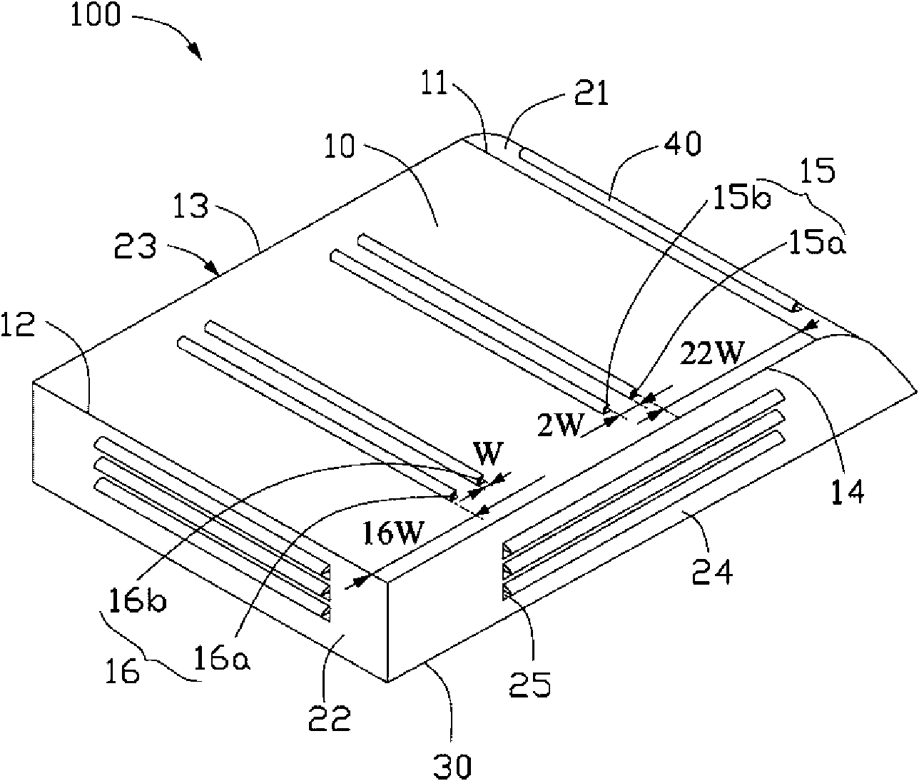
[0009] see figure 1 , is the lamp housing 100 provided by the present invention. The lamp housing 100 includes a top plate 10 , a first side wall 21 , a second side wall 22 , a third side wall 23 , a fourth side wall 24 and a rain shield 40 . The material of the lamp housing 100 can be metal alloy or plastic. In this embodiment, the lamp housing 100 is made of plastic.

[0010] In this embodiment, the top plate 10 is roughly rectangular, and the top plate 10 has a first edge 11, a second edge 12, a third edge 13 and a fourth edge 14, a first set of top plate cooling holes 15 and a second set of top plate Cooling hole 16. The first edge 11 is opposite to the second edge 12 . In this embodiment, the third edge 13 is opposite to the fourth edge 14 . In this embodiment, the first group of top plate heat dissipation holes 15 includes top plate heat dissipati...


PUM


Abstract

The invention provides a lamp housing, comprising a top plate and a side wall. The top plate is provided with a first edge, a second edge, a first group of top plate heat dissipation holes and a second group of top plate heat dissipation holes, wherein the first edge and the second edge are arranged correspondingly; each top plate heat dissipation hole has equivalent width and is in a strip type;the mutual spacing of the first group of top plate heat dissipation holes is twice of the width of the top plate heat dissipation holes; the mutual spacing of the second group of top plate heat dissipation holes is twice of the width of the top plate heat dissipation holes; the first group of top plate heat dissipation holes are arranged in parallel toward the center from the position which is 20to 24 times of the hole width distant from the first edge; the second group of top plate heat dissipation holes are arranged in parallel toward the center from the position which is 14 to 18 times ofthe hole width distant from the second edge; and the side wall is provided with side wall heat dissipation holes. In the lamp housing of the invention, top plate heat dissipation holes are opened on the top plate, thus being beneficial to natural convection of the air in the lamp housing, improving the heat dissipation efficiency of the lamp housing, and further reducing the temperature in the lamp housing.

Description

technical field [0001] The invention relates to a lamp housing, in particular to a lamp housing which utilizes air convection to dissipate heat. Background technique [0002] Light-emitting diodes (LEDs) have the characteristics of low power consumption and long life. Therefore, applying LEDs to lighting equipment can reduce maintenance costs and save energy. At present, it is common for indoor and outdoor lighting equipment, but the temperature of the LED substrate is the key factor affecting the luminous intensity and life. Therefore, when designing the housing of the LED lighting equipment, in addition to considering the appearance of the LED lighting equipment, heat dissipation performance must also be considered. [0003] At present, the heat dissipation methods of LED street lamps mainly adopt the direct heat dissipation method of fins, the forced heat dissipation method of fans or the natural convection heat dissipation method of opening holes. Most of the hole desi...

Claims


Application Information

Patent Timeline
Patent Type & Authority Applications(China)
IPC IPC(8): F21V15/02F21V29/00H01L23/367F21Y101/02
CPCF21V29/004F21V15/06F21V29/2293F21V29/15F21V29/83F21V29/507F21V15/01
Inventor 林俊宇张嘉淳
Owner HONG FU JIN PRECISION IND (SHENZHEN) CO LTD
Why Eureka
Try Eureka