
Energy saving magnetic head and control method thereof

An electromagnetic head and valve technology, applied in electromagnetic relays, electromagnets with armatures, detailed information of electromagnetic relays, etc., can solve problems such as waste of energy and equipment loss, reduce temperature rise, prolong service life, and reduce power consumption Effect

Inactive Publication Date: 2013-02-27
ZHEJIANG ZHONGFU FLUID MASCH CO LTD
View PDF5 Cites 0 Cited by
  • Summary
  • Abstract
  • Description
  • Claims
  • Application Information

AI Technical Summary

Problems solved by technology

In actual work, when the dynamic and static iron cores of the electromagnetic head are attracted together, the required suction force will become smaller, but the actual suction force will increase with the decrease of the gap, which not only wastes energy, but also gives The equipment itself brings a large loss

Method used


Image

  • Energy saving magnetic head and control method thereof
  • Energy saving magnetic head and control method thereof
  • Energy saving magnetic head and control method thereof

Examples


Embodiment Construction

[0034] The present invention will be described in further detail below in conjunction with the accompanying drawings.

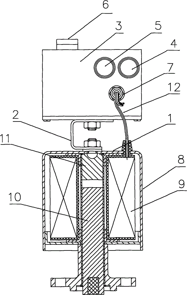
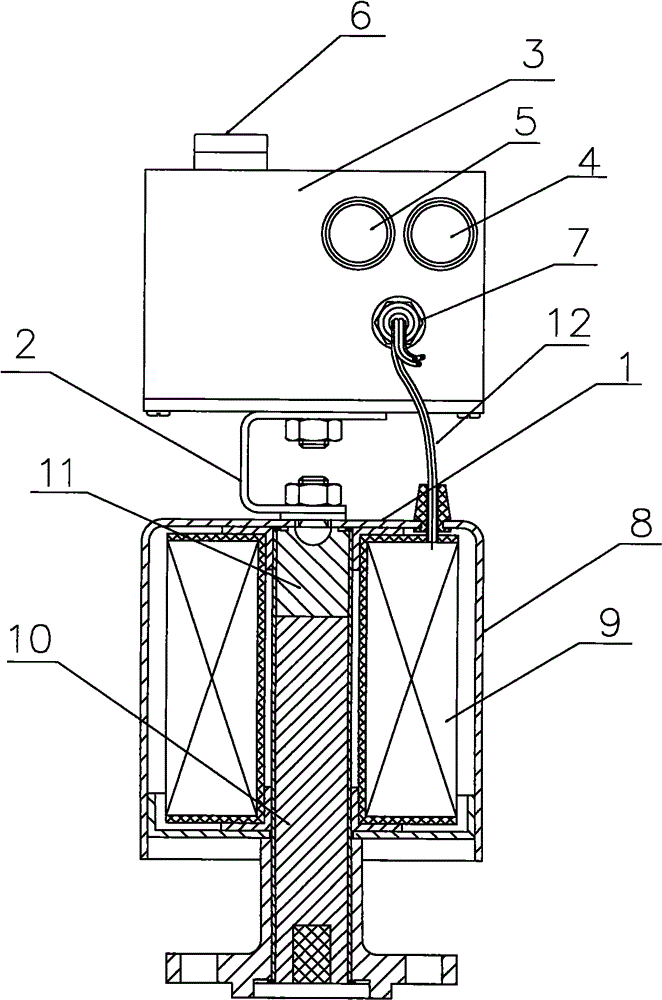
[0035] see figure 1 and figure 2 , an embodiment of the present invention includes a magnetic head main body 1 and a magnetic head control circuit, the magnetic head main body includes a magnetically conductive shell 8, a moving iron core 10, a static iron core 11 and a coil 9 that cooperate with each other, and the magnetically conductive There is an iron core passage in the shell, the static iron core is fixedly installed on the upper end of the iron core passage, the moving iron core is slidably connected in the iron core passage, the static iron core and the moving iron core There is a working air gap between them, the coil is arranged around the passage of the iron core, and the magnetically permeable shell is also provided with a through hole for the wire 12 to pass through.

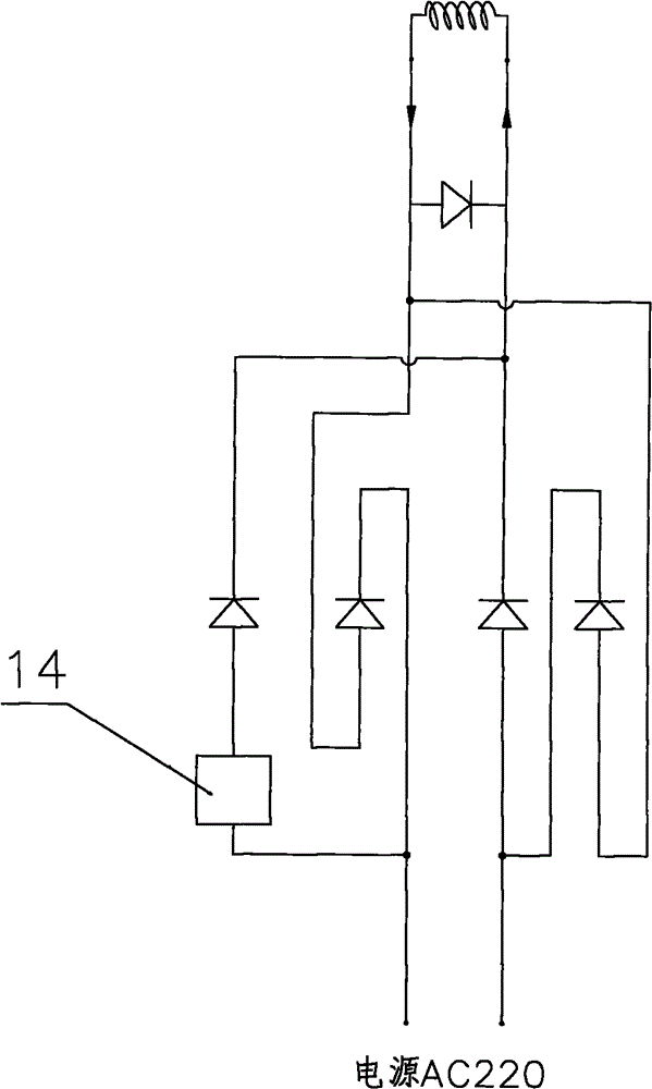
[0036] The energy-saving electromagnetic head also includes an electric c...


PUM


Abstract

The invention relates to and energy saving magnetic head and control method thereof. The energy saving magnetic head comprises a magnetic head body and a magnetic head control circuit, wherein the magnetic head control circuit connects with a coil in the magnetic head body through wires, and can change current in the coil according to real-time working condition of the magnetic head body; the energy saving magnetic head control method is that current of the coil of the magnetic head is controlled through the magnetic head control circuit, so that the current in the coil is large current the magnetic head is started, and the current in the coil is small current under stable working condition. Through changing the current of an input coil, the invention not only can save energy consumption,but also can restrain temperature rise of the coil, which is mainly used for various industrial electromagnetic valve, especially high power electromagnetic valve.

Description

technical field [0001] The invention relates to an energy-saving electromagnetic head and a control method for the energy-saving electromagnetic head, which can change the magnitude of the current input to the coil, and has the functions of energy saving and equipment protection. Background technique [0002] The existing electromagnetic head is equipped with a junction box, and the power is turned on through the switch of the junction box. After the coil is energized (usually the voltage through the electromagnetic head coil is 220V), the coil generates a magnetic field, and the magnetic field lines pass between the moving iron core and the static iron core. The working air gap is from the moving iron core to the static iron core, forming a magnetic field line transmission loop. Due to the mutual attraction between the moving iron core and the static iron core during the starting process, the gap between the two gradually decreases, thereby making the magnetic resistance al...

Claims


Application Information

Patent Timeline
Patent Type & Authority Patents(China)
IPC IPC(8): H01F7/18F16K31/06H01H47/02H01H50/64H01H3/38
Inventor 陈国顺
Owner ZHEJIANG ZHONGFU FLUID MASCH CO LTD
Learn More