
High-voltage terminal device for transformer

A high-voltage outgoing line and transformer technology, applied in the direction of transformer/inductor coil/winding/connection, etc., can solve the problems of uneven electric field distribution, easy nesting, etc., achieve uniform electric field distribution, reduce insulation distance, and eliminate internal cavity nests The effect of gas problems

Active Publication Date: 2010-02-24
TBEA SHENYANG TRANSFORMER GRP CO LTD +1
View PDF0 Cites 10 Cited by
  • Summary
  • Abstract
  • Description
  • Claims
  • Application Information

AI Technical Summary

Problems solved by technology

[0003] Aiming at defects such as uneven distribution of electric field and easy nesting of air in the cavity inside the pressure equalizing ball in the high-voltage outlet device for transformers in the prior art, the technical problem to be solved by the present invention is to provide a kind of uniform electric field distribution and a hollow space inside the equalizing ball. High-voltage outgoing line device for transformers with no cavity

Method used


Image

  • High-voltage terminal device for transformer
  • High-voltage terminal device for transformer
  • High-voltage terminal device for transformer

Examples


Embodiment 1

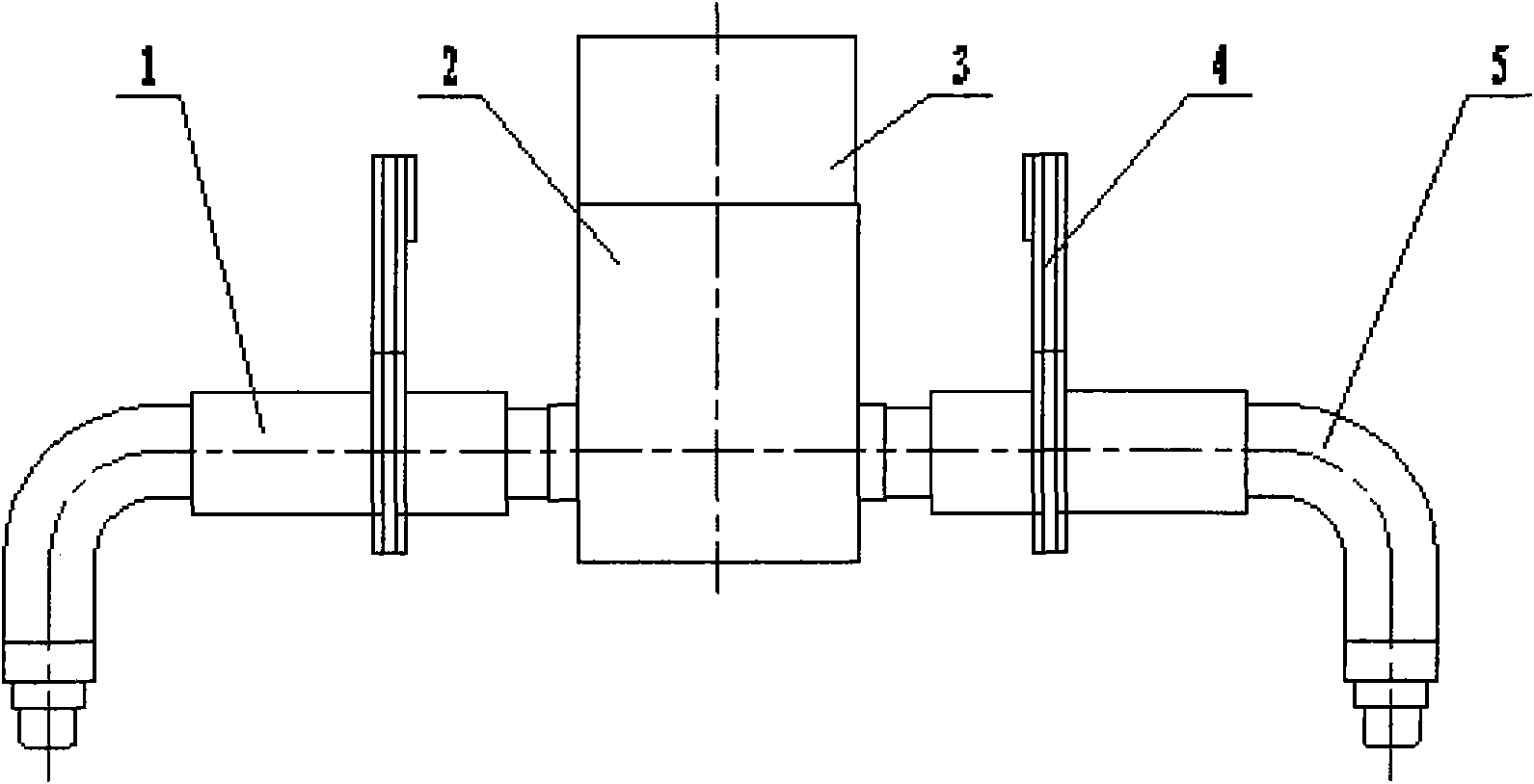
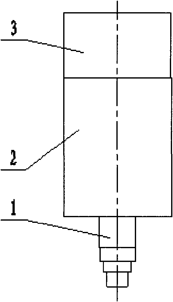
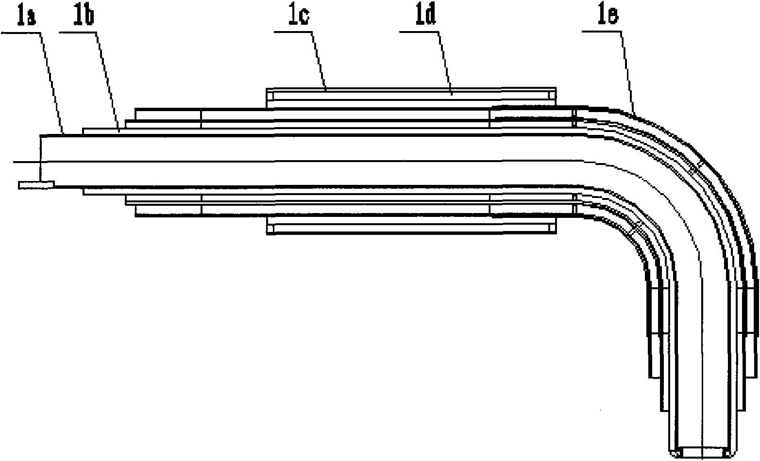
[0015] Such as figure 1 , 3 , 4 and 5, the utility model is applied to the high-voltage outlet of the transformer, including the outlet tube, the pressure equalizing ball 2, the movable paper tube 3, the wire clip 4, the copper braid 6, the fixing part 7 and the terminal 8, etc. In this embodiment, there are two outlet barrels (i.e., outlet barrels 1 and 5), which are inserted symmetrically from both sides of the pressure equalizing ball 2, and the outer surface of the equalizing ball 2 is tightly wrapped by hand with Insuldur heat-resistant crepe paper to ensure , no gap will be formed between the outer surface of the pressure equalizing ball and the insulation; the equalizing ball 2 is mainly composed of a shielding cylinder 2f, and an insulating layer 2g is arranged outside it, and a paper tube 2d is arranged on the outside of the insulating layer 2g through a stay 2e; the insulating layer The upper and lower parts of 2g are bent inward; the two sides of the lower part of ...

Embodiment 2

[0020] Such as figure 2 As shown, the difference from Embodiment 1 is that there is one outlet barrel 1, and the pressure equalizing ball 2 is inserted from the bottom and fixed.


PUM


Abstract

The invention relates to a high-voltage terminal device for a transformer, which is arranged at a high-voltage terminal of the transformer and is provided with a shielding ball and an outgoing line cylinder in insert connection with the shielding ball. The external surface of the shielding ball is wrapped by heat-resistance insulated paper, an insulated layer in an internal cavity is an extended part of the heat-resistance insulated paper, and an air pocket position of the part is poured with epoxy resin. The outgoing line cylinder is sequentially provided with a shielding tube, an insulated layer and a paper cylinder from the inside to the outside, wherein the paper cylinder has a plurality of layers; supporting bars are arranged between layers; and the insulated layer is insulated paperwrapped outside the shielding tube. The whole terminal device of the invention is greatly improved in working voltage due to uniform electric field distribution and reduces local discharge quantity bysolving the gas pocket problem in the internal cavity of the shielding ball. In addition, under a condition of the same insulation level, the insulation distance between electrodes is reduced.

Description

technical field [0001] The invention relates to an insulating device used in a high-voltage power transformer, in particular to a high-voltage outlet device for a transformer. Background technique [0002] The high-voltage outlet device for transformer is an insulation device used for the high-voltage outlet of the transformer. Its function is to effectively improve the distribution of the surrounding electric field and reduce the requirement for insulation distance. At present, when transformer manufacturers use high-voltage outlet devices, they design, develop and manufacture them according to the insulation level requirements and the space size inside the transformer to meet the technical requirements. However, due to technical reasons, the following problems often exist: (1) After the outlet device is dried, There is an uneven small gap between the outer surface of the equalizing ball and the insulation, which may cause an increase in the partial discharge during the tra...

Claims


Application Information

Patent Timeline
Patent Type & Authority Applications(China)
IPC IPC(8): H01F27/32
Inventor 王相中王健李桂苹
Owner TBEA SHENYANG TRANSFORMER GRP CO LTD
Learn More