
Container cell, in particular bottle cell, and container rack having such container cells

A chamber and container technology, applied in the field of container racks, can solve problems such as energy loss, and achieve the effect of simplifying the manufacturing process

Active Publication Date: 2010-02-24
KHS GMBH
View PDF2 Cites 3 Cited by
  • Summary
  • Abstract
  • Description
  • Claims
  • Application Information

AI Technical Summary

Problems solved by technology

However, the disadvantage of this production (connection) is that, for reasons of stability, such a container chamber made of plastic has a relatively high mass and thus a high heat capacity
During the operation of the container cleaning machine, significant energy losses are incurred due to temperature differences between the different treatment zones and due to the continuous heating and cooling of the container chambers during transport through the treatment zones

Method used


Image

  • Container cell, in particular bottle cell, and container rack having such container cells
  • Container cell, in particular bottle cell, and container rack having such container cells

Examples


Embodiment Construction

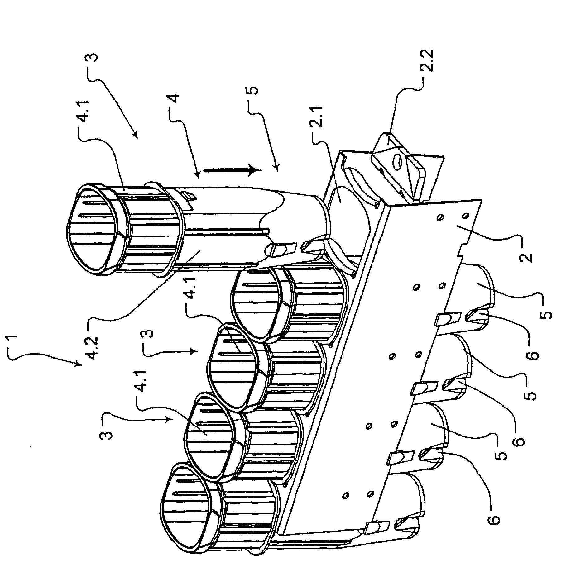
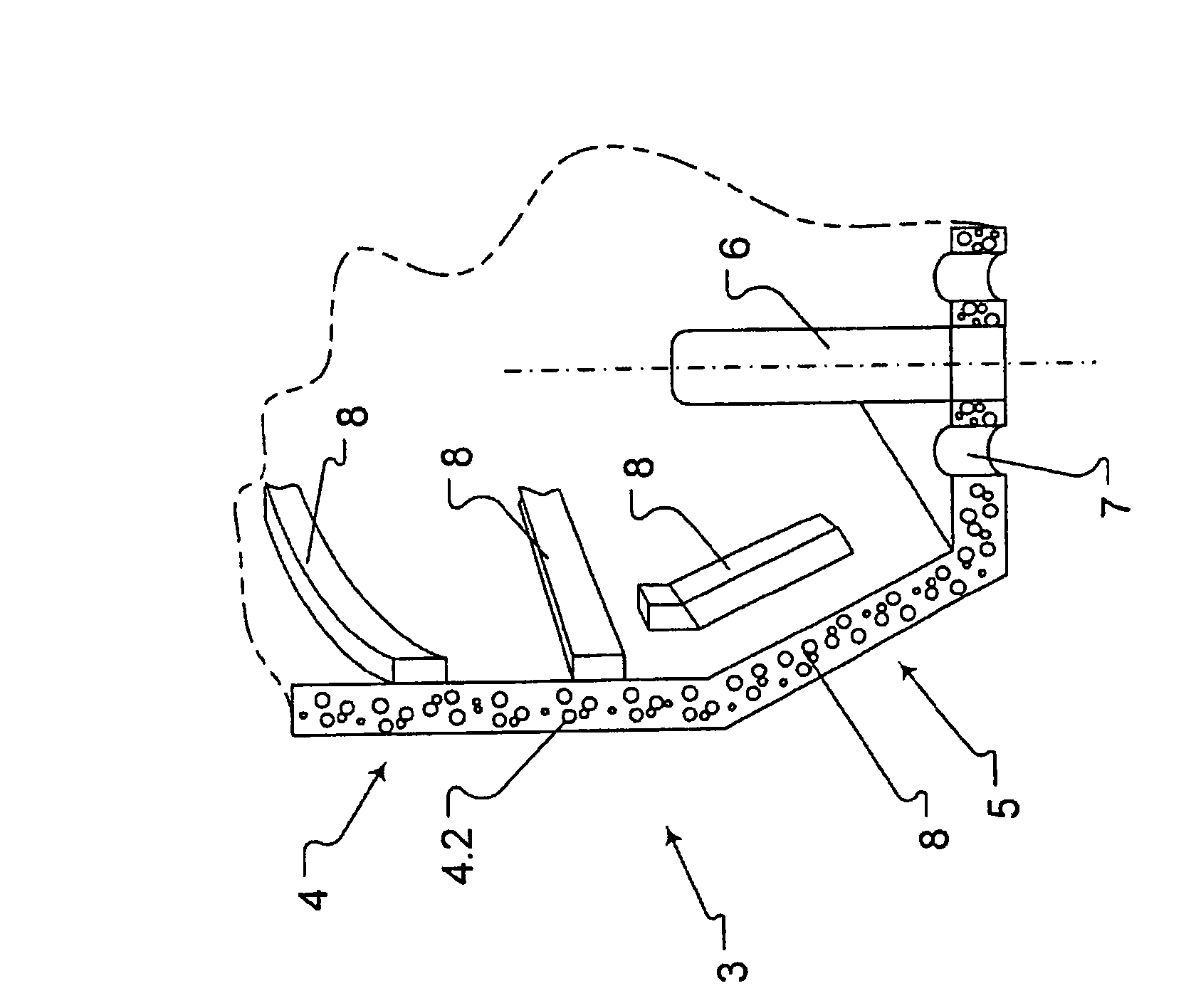
[0011] The container rack generally identified by the reference numeral 1 in the figure basically comprises a box-shaped carrier 2, for example made of steel, preferably corrosion-resistant steel; and a plurality of bottle or container compartments 3, wherein the A plurality of bottle compartments or container compartments 3 are each inserted into sockets 2 . 1 of the compartment carrier 2 with a good fit and are held on said compartment carrier in a torque-proof and precise and stable manner, for example by interlocking.

[0012] The container rack 1 is a component part of a container cleaning machine, not shown, for cleaning bottles or similar bottles of this type of container, and at the same time it is a special part of the conveyor system of the container cleaning machine. The system comprises a plurality of container racks 1 of the same type, which are respectively held with their chamber carriers 2 at both ends by means of fastening strips 2.2 on an endless conveying ele...


PUM


Abstract

The invention relates to a container cell of a container-cleaning machine, in particular bottle-cleaning machine, having a cell interior which is enclosed by a lateral cell surface and is intended for accommodating a container which is to be cleaned.

Description

technical field [0001] The invention relates to a container compartment according to the preamble of claim 1 and to a container rack according to the preamble of claim 6 . Background technique [0002] Container chambers or bottle chambers are known as component parts of container racks or bottle racks in container or bottle cleaning machines and are transported past the respective container by means of a conveying system formed by a plurality of container or bottle racks. A container or bottle chamber is used in a container or bottle cleaning machine for accommodating said containers during the different cleaning and treatment zones of the container or bottle cleaning machine (see patent publication DE 19542673 A1). [0003] Also known are container compartments or bottle compartments (see patent publication DE4242375A1) whose walls or side surfaces respectively comprise a cylindrical or polygonal part and an adjoining constriction (mouth region), wherein the constriction ...

Claims


Application Information

Patent Timeline
Patent Type & Authority Applications(China)
IPC IPC(8): B08B9/42
CPCB08B9/42
Inventor B·莫利托
Owner KHS GMBH
Learn More