Method for forming color filter

A color filter, color photoresist technology, applied in the direction of filter, photoengraving process coating equipment, etc., can solve the problems of reducing process efficiency, large number of nozzles, long spraying time and so on

Inactive Publication Date: 2010-03-03
AU OPTRONICS CORP
View PDF0 Cites 6 Cited by
  • Summary
  • Abstract
  • Description
  • Claims
  • Application Information

AI Technical Summary

Problems solved by technology

However, in this way, the spraying time for a single sub-pixel 24 may be longer and the number of spray heads required will be larger, greatly reducing the process efficiency

Method used


Image

  • Method for forming color filter
  • Method for forming color filter
  • Method for forming color filter

Examples


Embodiment Construction

[0019] The following method for forming a color filter according to the present invention will be described in detail with specific examples in conjunction with the attached drawings. However, the provided examples are not intended to limit the scope of the present invention, and the description of the method flow steps is not intended to The order of execution is limited, and any execution flow recombined from method steps to produce methods with equal efficacy is within the scope of the present invention. The drawings are for illustration purposes only and are not drawn to original scale.

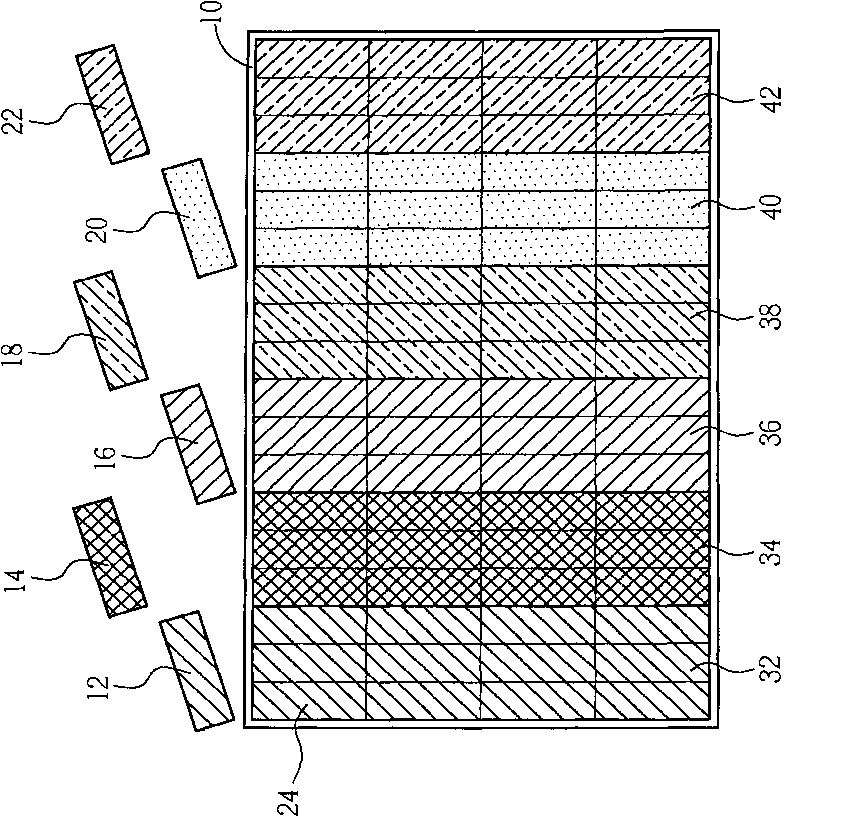
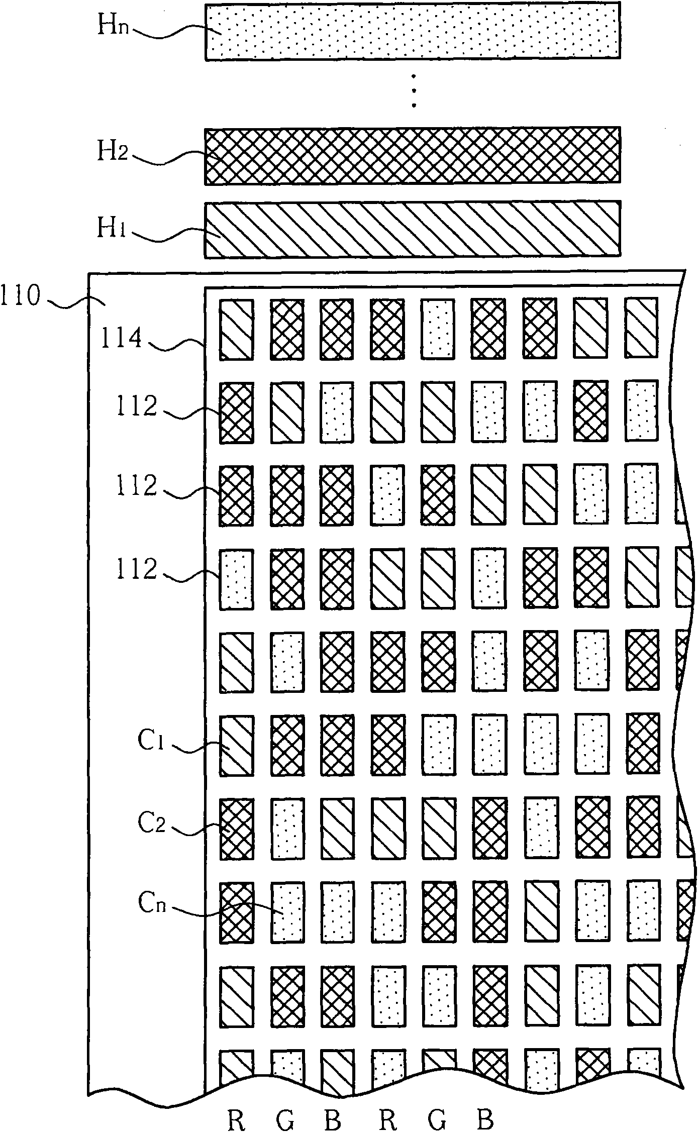
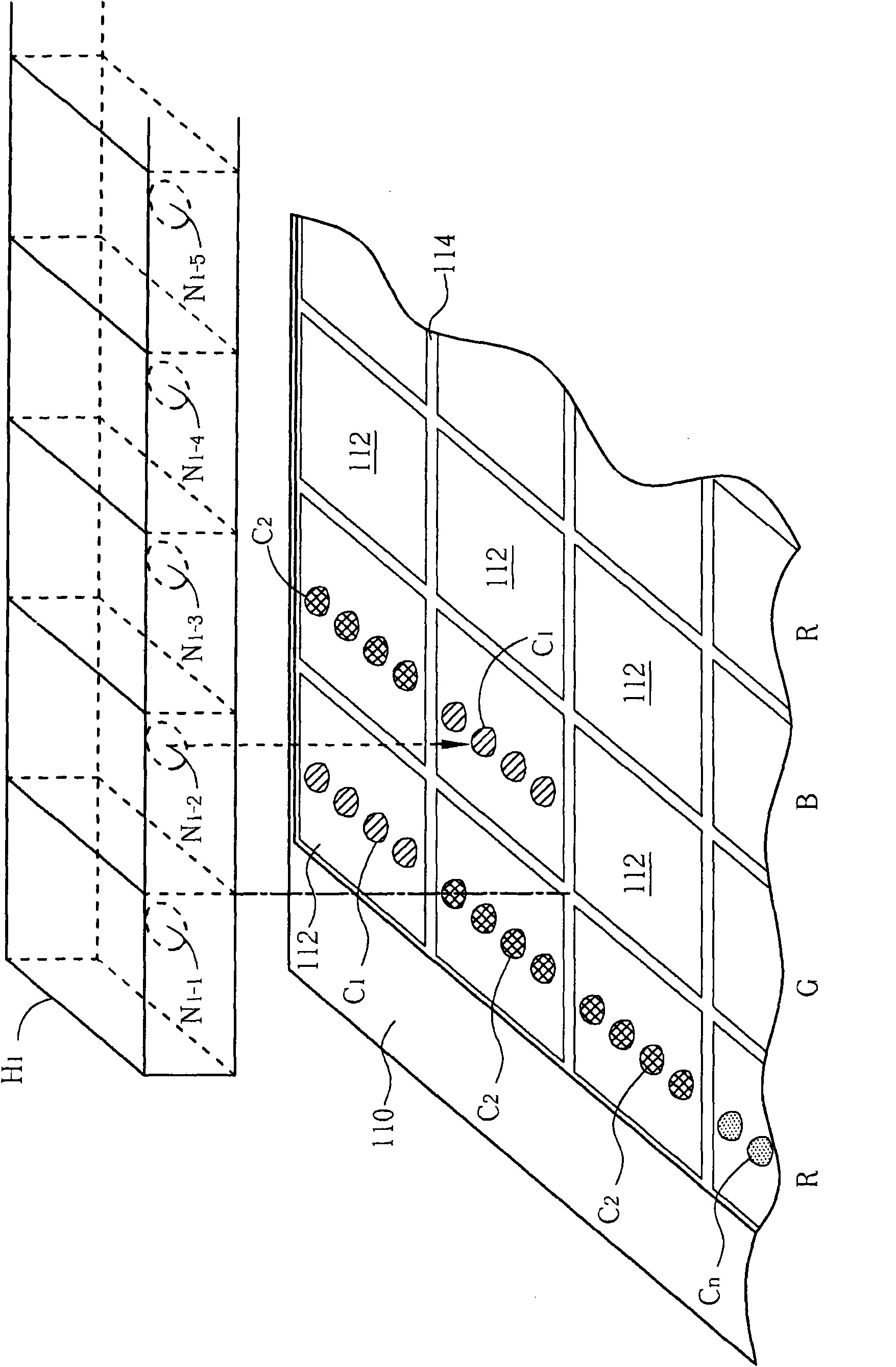
[0020] Figure 2 to Figure 4 It is a schematic diagram of the method for forming a color filter according to the first embodiment of the present invention. like figure 2 As shown, the present invention can provide at least one coating device, such as an inkjet device, and the coating device can include a plurality of shower heads, such as n shower heads H 1 、H 2 ,...,H n , where n i...


PUM


Abstract

The invention provides a method for forming a color filter, comprising the step of respectively randomly spraying sub-pixel zones in each row. The spraying comprises the steps: randomly selecting oneof spray heads, spraying color photoresist materials to the selected sub-pixel zone with the selected spray head till that the color photoresist materials in the sub-pixel zone reaches the discharge amount of the photoresist required by the sub-pixel zone. The color photoresist materials positioned in the same sub-pixel zone is only sprayed with the same spray head, and the color photoresist materials positioned in the same sub-pixel zones in the each row are sprayed by the at least two spray heads.

Description

technical field [0001] The invention relates to a method for forming a color filter, especially a method for forming a color filter by coating with a plurality of printheads. Background technique [0002] Liquid crystal displays have become the mainstream products in the monitor and thin TV market due to their advantages of thinness, lightness, shortness and power saving. For liquid crystal displays, color filters are one of the most important key components. Only through the filtering effect of color filters can liquid crystal displays display brightly colored images. [0003] As the specifications and sizes of liquid crystal displays continue to increase, the requirements for the characteristics of color filters are also increasing. In terms of the current traditional color filter manufacturing technology, the color filter produced by the pigment dispersion method is more capable. In line with the needs of the current stage, it has become a more common method among variou...

Claims


Application Information

Patent Timeline
IPC IPC(8): G02B5/20G03F7/16
Inventor 陈重伊王薇雅林永龙周胜国阳靖宇李淑琴
Owner AU OPTRONICS CORP
Why Eureka
Try Eureka