
Transmission device used for optical cable repeated bending testing machine

A transmission device, repeated bending technology, applied in measuring devices, using repeated force/pulse force to test the strength of materials, instruments, etc., can solve the problems of motor burnout, excessive forward and reverse times, etc., and achieve reliable movement and simple structure. , the effect of low cost

Inactive Publication Date: 2010-03-10
ZHENGZHOU SHIJIA COMM TECH
View PDF0 Cites 9 Cited by
  • Summary
  • Abstract
  • Description
  • Claims
  • Application Information

AI Technical Summary

Problems solved by technology

[0005] The purpose of the present invention is to provide a transmission device for optical cable repeated bending test machine, so as to solve the problem of motor burnout caused by too many times of forward and reverse rotation of the motor in the prior art

Method used


Image

  • Transmission device used for optical cable repeated bending testing machine
  • Transmission device used for optical cable repeated bending testing machine

Examples


Embodiment Construction

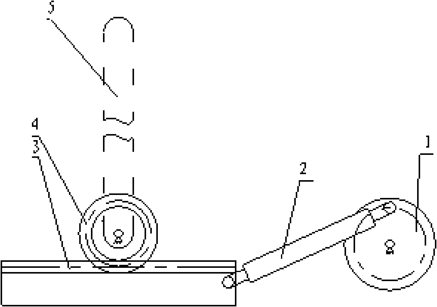
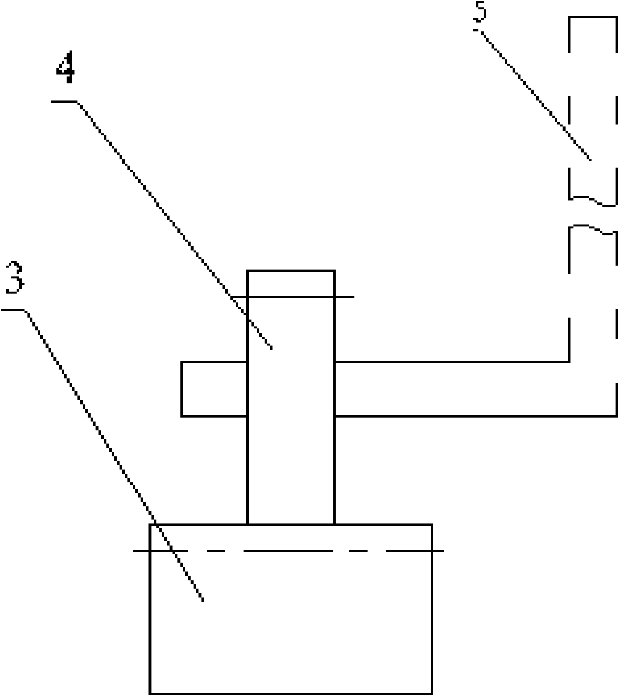
[0011] exist figure 1 Among them, a transmission device for an optical cable repeated bending test machine includes a crank slider mechanism, the crank slider mechanism includes a turntable 1, a connecting rod 2, and a toothed slider 3, and one end of the connecting rod 2 is hingedly arranged on the disk surface of the turntable 1 , the turntable 1 rotates around its center, the other end of the connecting rod 2 is hinged with one end of the toothed slider 3, and the toothed slider 3 is meshed with the gear 4 to form a rack and pinion transmission mechanism, and one side of the gear 4 is radially A fork 5 is fixedly arranged.

[0012] When moving, the motor (not shown in the figure) can be used to drive the turntable 1 to rotate in one direction around its center, and drive the connecting rod 2 to do plane movement, the connecting rod 2 is hinged with one end of the toothed slider 3, and the toothed slider 3 Driven by the rod 2, it makes a reciprocating linear motion, and the...


PUM


Abstract

The invention relates to a transmission device used for an optical cable repeated bending testing machine, comprising a crank sliding block mechanism; the sliding block of the crank sliding block mechanism is a strip-shaped sliding block, one side surface of which is provided with transmission teeth; a sliding block with teeth is meshed with a gear so as to form a gear rack transmission mechanism;and the gear is used for driving a swinging rod to swing. The sliding block of the crank sliding block mechanism is provided with transmission teeth meshed with the gear; the sliding block with teethand the gear form the gear rack transmission mechanism; the gear is used for driving the swinging rod thereon to swing; the sliding block with teeth of the crank sliding block mechanism drives the gear to rotate in a reciprocating manner so as to change the unidirectional rotating movement of the crank into reciprocating rotating movement of the gear; with the reciprocating rotation of the gear,the swinging rod outputs swinging movement and can realize swinging by plus or minus 90 degrees by adjusting the length of the crank. The transmission device has simple structure, reliable movement, low cost, no limitation for movement of the swinging rod and larger swinging angle.

Description

technical field [0001] The invention relates to a transmission device for an optical cable repeated bending test machine. Background technique [0002] The current optical cable repeated bending test machine is designed for outdoor optical cables. Its working process is roughly as follows: take a section of optical cable sample, tighten the optical cable through both ends of the optical cable, and place the middle part of the optical cable in a pair of equal-sized bending testers. Between the wheels, swing one end of the optical cable left and right, and the part of the optical cable between the two bending test wheels will bend on the peripheral surface of the bending test wheel. Based on this working process, the current optical cable repeated bending test machine includes frame, A motor, a transmission device and a pendulum rod are arranged on the upper end of the frame. The transmission device includes a worm connected to the motor and a worm gear meshed with the worm ge...

Claims


Application Information

Patent Timeline
Patent Type & Authority Applications(China)
IPC IPC(8): G01N3/32G01N3/26G01N3/02
Inventor 李然山
Owner ZHENGZHOU SHIJIA COMM TECH
Learn More