Repeated bending test equipment of optical cable

A technique of repeated bending and bending test, applied in the direction of applying repetitive force/pulse force to test the strength of materials, measuring devices, instruments, etc. Low heat and the effect of increasing friction

Inactive Publication Date: 2011-02-02
ZHENGZHOU SHIJIA COMM TECH
View PDF0 Cites 11 Cited by
  • Summary
  • Abstract
  • Description
  • Claims
  • Application Information

AI Technical Summary

Problems solved by technology

[0007] The purpose of the present invention is to provide a kind of repeated bending test equipment for optical cable, so as to solve the problem of motor burning due to too many times of forward and reverse rotation of the motor in the prior art

Method used


Image

  • Repeated bending test equipment of optical cable
  • Repeated bending test equipment of optical cable
  • Repeated bending test equipment of optical cable

Examples


Embodiment Construction

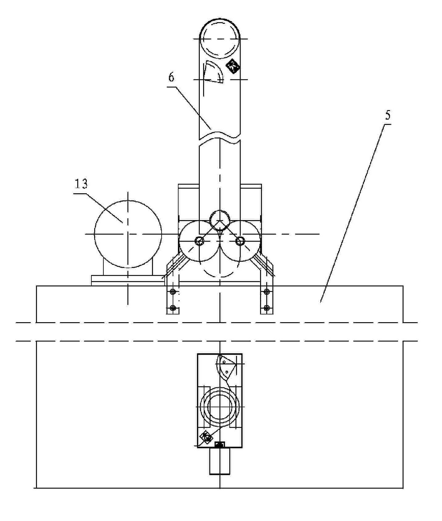
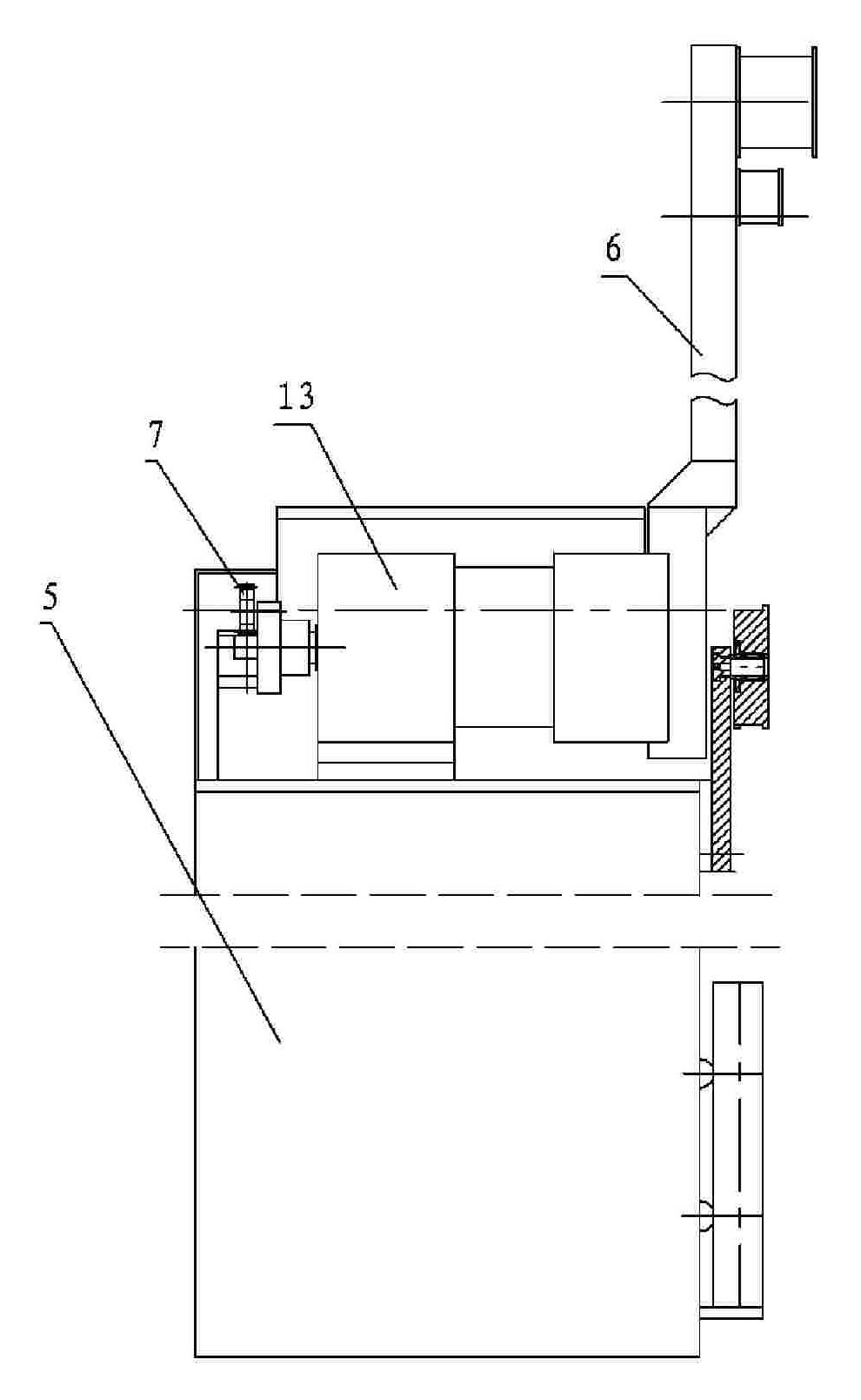
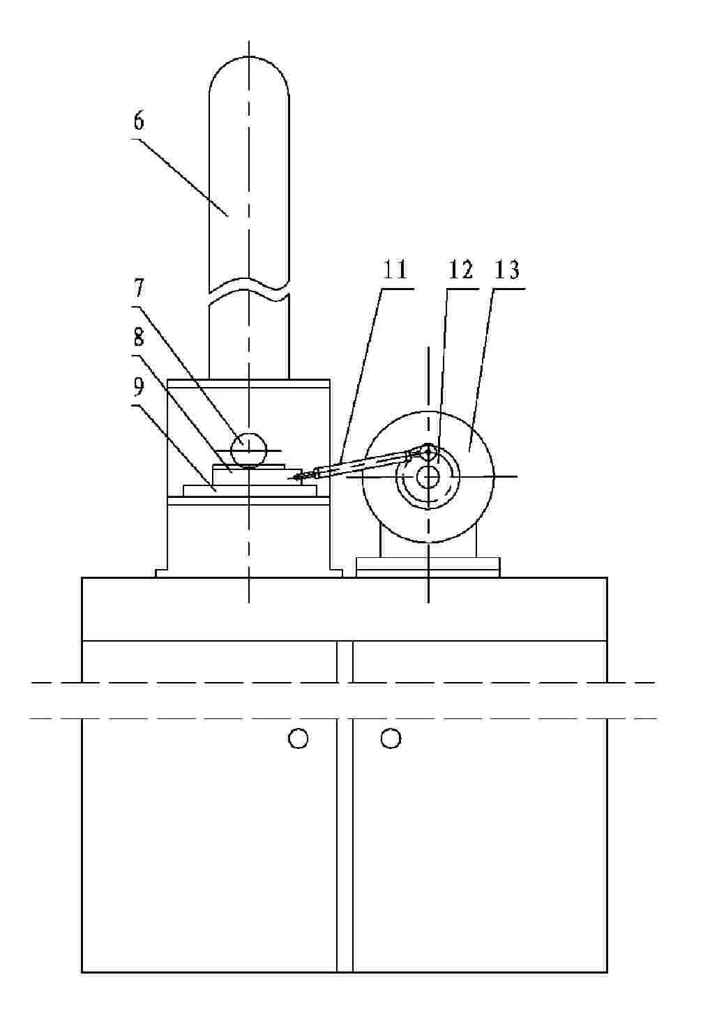
[0024] exist figure 1 , figure 2 , image 3 , Figure 4 , Figure 5 Among them, a kind of optical cable repeated bending test equipment, comprises frame 5, is provided with motor 13 on frame 5, is provided with the motor turntable 12 that acts as crank on the output shaft of motor 13, and one end of connecting rod 11 is hinged on the motor turntable 12 On the disk, the other end of the connecting rod 11 is hinged to one end of the toothed slider 8, the toothed slider 8 is slidably installed on the frame 5 through the linear bearing 9, and the gear 7 is assembled on the frame 5 through its rotating shaft. 7 is meshed with the toothed slider 8 for transmission, and one end of the rotating shaft of the gear 7 is fixedly provided with a swing rod 6, and the swing end of the swing rod 6 is fixedly provided with an upper fixture, and the lower part of the frame 5 is provided with a vertical slide rail. The sliding assembly is provided with a counterweight slide block, and a low...


PUM


Abstract

The invention relates to a repeated bending test equipment of an optical cable, comprising a rack and a swinging rod, wherein the rack is provided with a motor; an output end of the motor is connected with a transmission device in a transmission manner; the side surface of the rack is provided with two bending testing wheels; the side surface of the rack is provided with a vertical sliding rail below the two bending testing wheels; the sliding rail is assembled with a counterweight sliding block which is provided with a lower clamp; the swinging end of the swinging rod is provided with an upper clamp; the transmission device comprises a crank sliding block mechanism; the sliding block of the crank sliding block mechanism is a strip-shaped sliding block, one side surface of which is provided with transmission teeth; the sliding block with teeth is meshed with a gear so as to form a gear rack transmission mechanism; and the swinging rod and the gear are fixedly connected into a whole along the radial direction of the gear. The motor drives a crank of the crank sliding block mechanism to rotate unidirectionally, the sliding block drives the gear to rotate in a reciprocating manner bytransmission teeth arranged thereon, and the swinging rod fixedly arranged on the gear outputs swinging. The motor can obtain swinging of the swinging rod without the need of positive rotation and negative rotation.

Description

technical field [0001] The invention relates to an optical cable repeated bending test equipment. Background technique [0002] With the start of 3G (3rd generation mobile communication) and FTTH (fiber-to-the-home), with the vigorous development of access network and customer premises network, and with the continuous decline in the price of optical receiving devices, the market for indoor optical cables has been steadily expanding year by year . Indoor optical cables are thin and soft, easy to install, weak in mechanical strength, and narrow in temperature range. Compared with outdoor optical cables, the requirements for mechanical properties such as tensile strength, lateral pressure resistance, and impact resistance are lower. However, the indoor space is small, there are many turns, and the bending probability is high, so the requirements for the repeated bending performance of indoor optical cables are higher. In order to make indoor optical cables suitable for norma...

Claims


Application Information

Patent Timeline
Patent Type & Authority Patents(China)
IPC IPC(8): G01N3/34G01N3/04
Inventor 何伟李然山
Owner ZHENGZHOU SHIJIA COMM TECH
Why Eureka
Try Eureka