
Computer system and method for monitoring bus of same

A computer system, bus monitoring technology, applied in the computer field, can solve the problems of increasing system volume, complex VME bus interface, and large number

Inactive Publication Date: 2010-03-10
HUAWEI TECH CO LTD
View PDF0 Cites 21 Cited by
  • Summary
  • Abstract
  • Description
  • Claims
  • Application Information

AI Technical Summary

Problems solved by technology

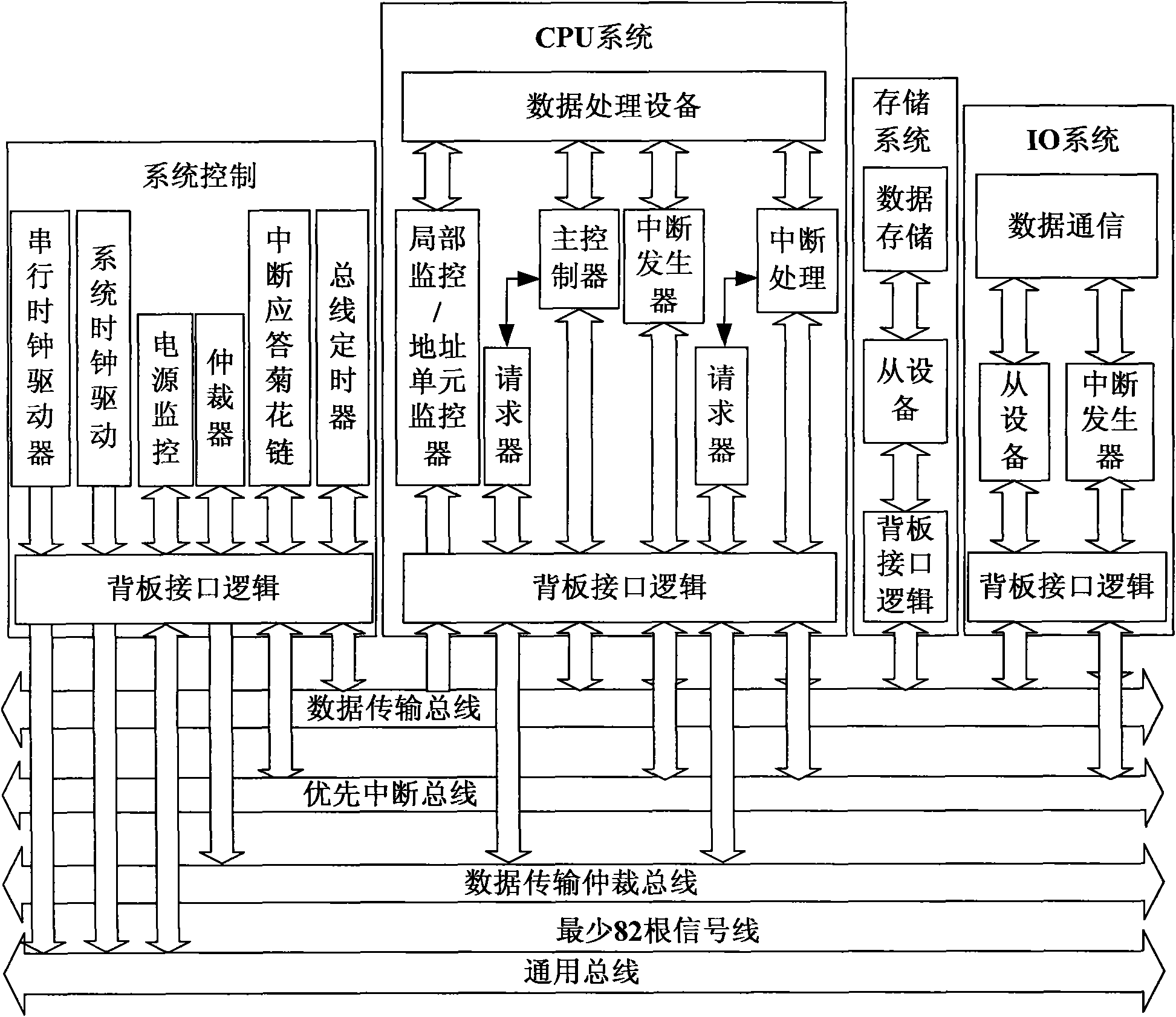
[0006] In the process of realizing the present invention, the inventor finds that the prior art has at least the following disadvantages: at least 82 VME bus signal lines are required in the computer system, which is a large number and increases the volume of the system; The chip is completed and the cost is high

Method used


Image

  • Computer system and method for monitoring bus of same
  • Computer system and method for monitoring bus of same
  • Computer system and method for monitoring bus of same

Examples


Embodiment Construction

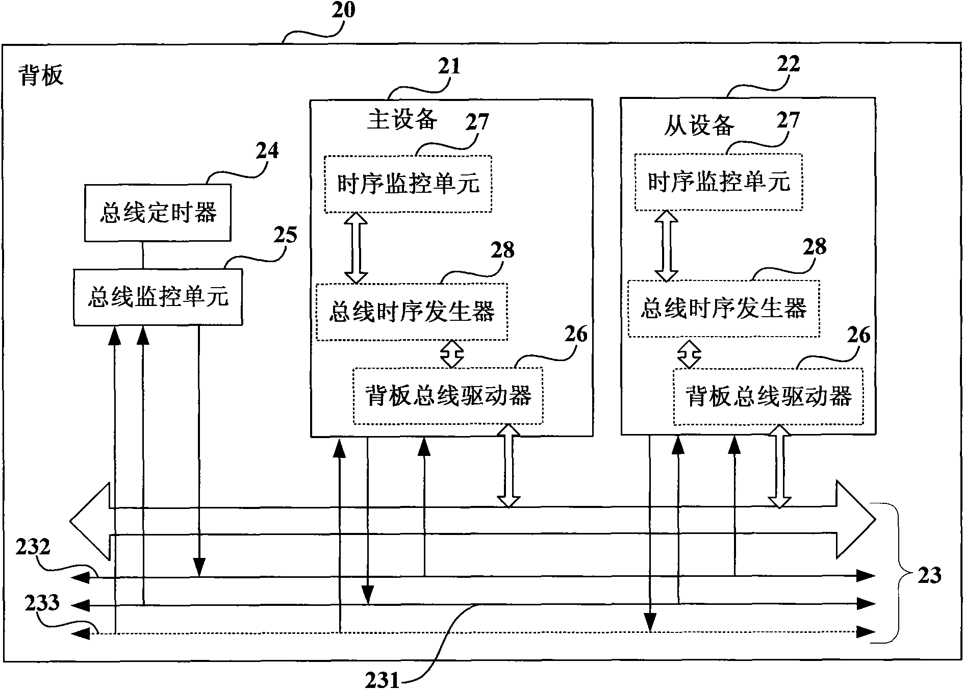
[0034] figure 2 It is a schematic structural diagram of a computer system provided by an embodiment of the present invention. The computer system includes a master device 21 on a backplane 20 , a slave device 22 , a backplane bus 23 , a bus timer 24 and a bus monitoring unit 25 . The master device 21 is connected to the slave device 22 through the backplane bus 23 . The backplane bus 23 may include: an address latch enabling signal line 231 and a bus error signal line 232 . The address latch enable signal line 231 is used to transmit an address latch enable signal (ALE). The bus error signal line 232 is used to transmit the bus error signal (BERR#). The bus monitoring unit 25 is connected to the address latch enabling signal line 231 and the bus error signal line 232, and is used to start the bus timer 24 to count when receiving ALE through the address latch enabling signal line 231 ; When the bus timer 24 is overtime, send BERR# through the bus error signal line 232.

...


PUM


Abstract

The invention relates to a computer system and a method for monitoring a bus of the computer system. The system comprises a master device, a slave device, a back plate bus and a bus timer, wherein themaster device is connected with the slave device by the back plate bus. The back plate bus comprises an address latch enabling signal line and a bus error signal line, wherein the address latch enabling signal line is used for transmitting an address latch enabling signal, and the bus error signal line is used for transmitting a bus error signal. The computer system also comprises a bus monitoring unit, wherein the bus monitoring unit is connected with the address latch enabling signal line and the bus error signal line and used for starting the bus timer to time when receiving the bus address latch enabling signal by the address latch enabling signal line and for transmitting the bus error signal by the bus error signal line when the bus timer is overtime.

Description

technical field [0001] The invention relates to the field of computer technology, in particular to a computer system and a bus monitoring method of the computer system. Background technique [0002] Computer systems are widely used in IT, telecommunications, industrial control, transportation, aerospace and other fields. The backplane bus in the computer system is used to realize the connection of different types of devices, and it is a set of transmission lines that provide signal transmission for multiple functional components. Computer systems in different application fields and occasions have different forms of backplane buses. [0003] With the development of computer technology and network technology, the backplane bus has experienced the development of parallel buses such as VME, ISA / PCI, and point-to-point interconnections such as PCI-E. Moreover, with the development of technology in the security field, such as industrial control, transportation, aerospace and oth...

Claims


Application Information

Patent Timeline
Patent Type & Authority Applications(China)
IPC IPC(8): G06F11/30G06F13/38
Inventor 谢林清
Owner HUAWEI TECH CO LTD
Learn More