
Disaster relieving system and method

A subsystem and disaster technology, applied in the field of disaster relief systems, can solve problems such as complex structures, difficulties, and disaster relief technologies that are difficult to meet expectations

Active Publication Date: 2010-03-10
北京英特威视科技有限公司
View PDF0 Cites 14 Cited by
  • Summary
  • Abstract
  • Description
  • Claims
  • Application Information

AI Technical Summary

Problems solved by technology

[0002] With the continuous development of human civilization and society, people are facing a series of new security issues, such as the security of special spaces. The so-called special spaces refer to tall buildings, public buildings deep underground, and traffic tunnels. The structure of the disaster is complex, so the accompanying new security issues make it difficult for traditional disaster relief techniques to achieve the intended purpose
Take the subway system as an example. At present, many subway transfer stations are tens of meters deep underground. When man-made or non-man-made disasters occur in these underground areas, such as natural disasters, terrorist attacks or fires, etc., the disaster relief work in the underground areas is very difficult. Large uncertainties and risks. After a disaster occurs, it is very difficult to rescue personnel, control the disaster, or fight the fire. Rescuers are often unable to go deep underground. This requires the development of a new type of disaster relief system.
[0003] At present, people are studying the problem of disaster relief in special spaces through the use of disaster relief devices such as robots and aircraft. By using these disaster relief devices, disaster relief personnel do not have to go deep into the disaster area. However, these disaster relief devices do not integrate early detection of disasters and automatic implementation. Disaster relief and integration, but unable to achieve purposeful and systematic disaster relief work

Method used


Image

  • Disaster relieving system and method
  • Disaster relieving system and method
  • Disaster relieving system and method

Examples


Embodiment Construction

[0125] The specific implementation manners of the present invention will be further described in detail below in conjunction with the accompanying drawings and embodiments.

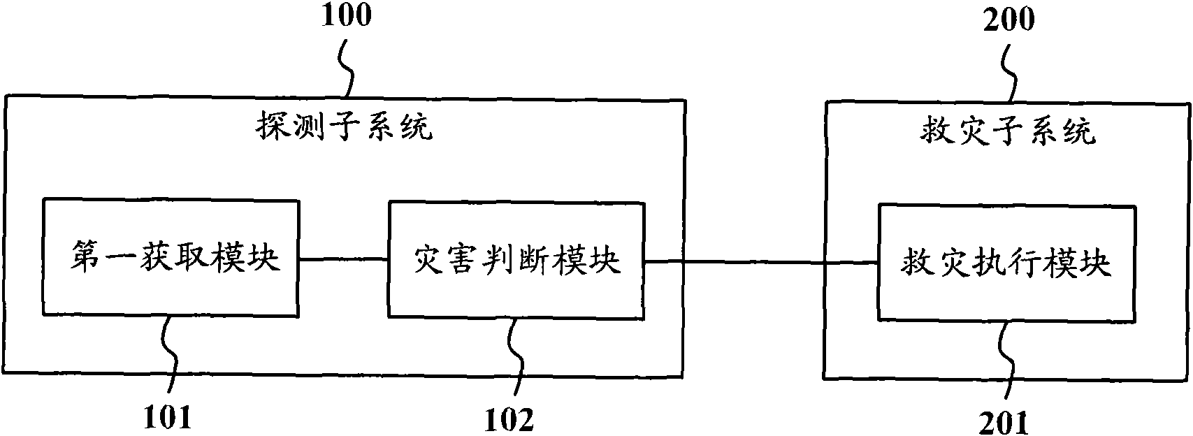
[0126] Such as figure 1 Shown is a schematic structural diagram of a disaster relief system according to an embodiment of the present invention, and the disaster relief system includes:

[0127] Detection subsystem 100 and disaster relief subsystem 200;

[0128] The detection subsystem 100 is used to perform early detection of disasters, including:

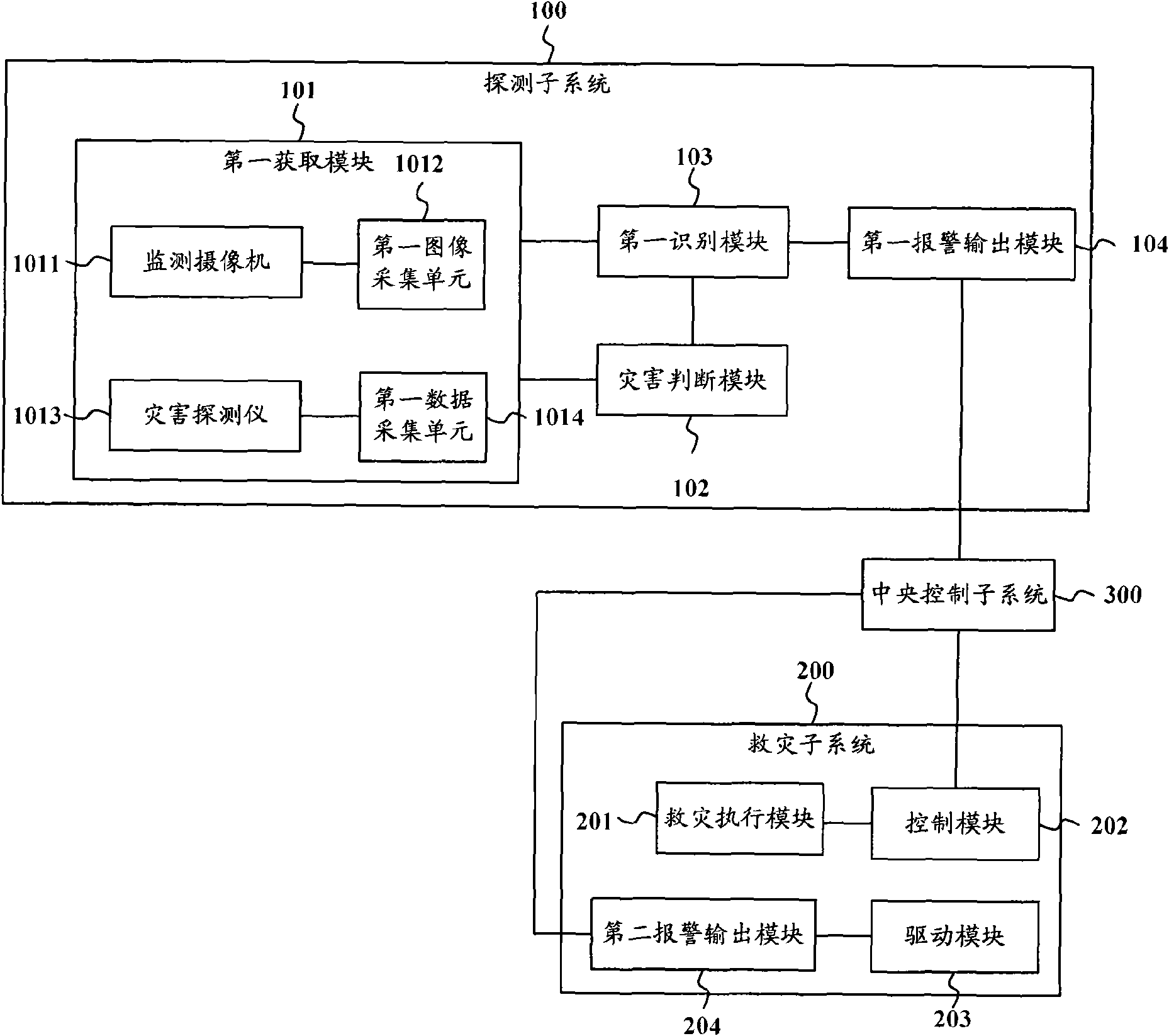
[0129] The first acquiring module 101 is configured to acquire disaster monitoring information of the protected area. The disaster monitoring information may be the monitoring image of the protected area, or the environmental monitoring information of the protected area, and the environmental monitoring information may be the temperature, the concentration of toxic gas or combustible gas, etc. in the protected area.

[0130] A disaster judgment module 102, c...


PUM


Abstract

The invention provides disaster relieving system and method. The disaster relieving system comprises a detecting subsystem and a disaster relieving subsystem; the detecting subsystem comprises a firstacquisition module used for acquiring disaster monitoring information in a protection zone and a disaster judgment module connected with the first acquisition module and used for judging whether a disaster happens or not according to the disaster monitoring information; and the disaster relieving subsystem comprises a disaster relieving execution module connected with the disaster judgment moduleand used for executing disaster relief when the disaster happens. The invention integrates early detection of disasters and automatic disaster relief into a whole, thereby improving the disaster preventing and relieving capacity of the disaster relieving system.

Description

technical field [0001] The invention relates to the technical field of disaster relief, in particular to a disaster relief system and method. Background technique [0002] With the continuous development of human civilization and society, people are facing a series of new security issues, such as the security of special spaces. The so-called special spaces refer to tall buildings, public buildings deep underground, and traffic tunnels. The structure of disaster relief is complex, so the accompanying new security issues make it difficult for traditional disaster relief techniques to achieve the intended purpose. Take the subway system as an example. At present, many subway transfer stations are tens of meters deep underground. When man-made or non-man-made disasters occur in these underground areas, such as natural disasters, terrorist attacks or fires, etc., the disaster relief work in the underground areas is very difficult. With large uncertainties and risks, after a disa...

Claims


Application Information

Patent Timeline
IPC IPC(8): G08B21/02G08B21/10G08B25/00H04N7/18
Inventor 丁国锋
Owner 北京英特威视科技有限公司
Learn More