Real-time monitoring method for power quality monitoring system and terminal running state

A technology for power quality monitoring and operating status, applied in the direction of measuring electrical variables, information technology support systems, measuring electricity, etc., can solve problems such as imperfect monitoring means, no software or method of power quality monitoring system, and low power quality of the power grid

Active Publication Date: 2010-06-09
SHANGHAI MUNICIPAL ELECTRIC POWER CO +2
View PDF0 Cites 26 Cited by
  • Summary
  • Abstract
  • Description
  • Claims
  • Application Information

AI Technical Summary

Problems solved by technology

Coupled with imperfect monitoring methods, operation, external interference and various faults, etc., power quality problems have become increasingly prominent
[0004] Especially with the large-scale application of direct current transmission, metal melting furnace, rectification equipment, high-power thyristor rectification device and power electronic devices, the power quality problem of public power grid is becoming more and more serious, and some areas have approached or exceeded the power quality index limit stipulated by the national standard. value, resulting in the low quality of power supplied by the power grid to other users, making it impossible for the power grid and user equipment to operate safely and economically
[0005] In order to improve the power quality, a corresponding power quality monitoring system is required to monitor the power quality, obtain accurate power quality information, and perform statistics and calculations on the power quality information. However, in the actual construction and use of the power quality monitoring system, It is often found that the monitoring data is lost due to failure of system software, hardware or monitoring terminal devices
At present, there is no relevant software or method specifically for monitoring the operation status of this power quality monitoring system

Method used


Image

  • Real-time monitoring method for power quality monitoring system and terminal running state
  • Real-time monitoring method for power quality monitoring system and terminal running state

Examples


Embodiment Construction

[0034] The present invention will be further described below in conjunction with accompanying drawing.

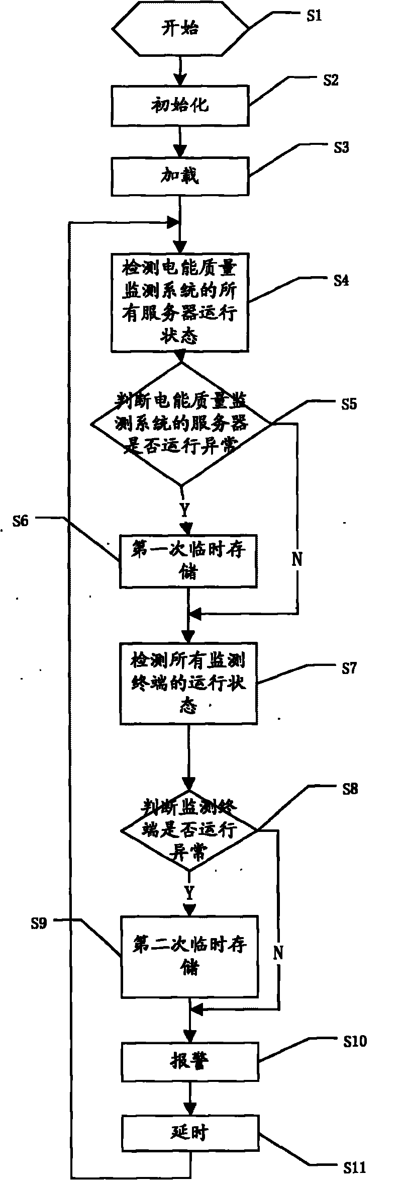
[0035] see figure 1 , a real-time monitoring method for power quality monitoring system and terminal operating status, real-time monitoring of power quality monitoring system and monitoring terminal through network topology map or GIS geographic information map, and displaying fault information, wherein, network topology The picture shows the network topology diagram of the power quality monitoring system. When any software and hardware of the system fail, the location of the failure and the cause of the failure are displayed through the network topology diagram, including the following steps:

[0036] Step S1, start step;

[0037] Step S2, the initialization step, initializes the GIS geographic information map;

[0038] Step S3, the loading step, loads the monitoring site information corresponding to the monitoring terminal on the GIS geographic information map;

[0039...


PUM


Abstract

The invention discloses a real-time monitoring method for a power quality monitoring system and a terminal running state; a network topological graph or a GIS geographic information map is adopted to carry out real-time monitoring to the power quality monitoring system and the monitoring terminal, and the fault message is displayed; the real-time monitoring method comprises the following steps: starting, initialization, loading, running state detection of all servers of the power quality monitoring system, judging whether the running of the servers of the power quality monitoring system is normal, first temporary storage, running state detection of all the monitoring terminals, judging whether the running of the monitoring terminal is normal, second temporary storage, alarming and time delaying; the real-time monitoring method for the power quality monitoring system and the terminal running state can monitor the power quality monitoring system and the terminal monitoring, ensure to find problems timely and solve the problems timely, and ensure the integrity of the monitoring data.

Description

technical field [0001] The invention relates to the field of power quality, in particular to a real-time monitoring method for a power quality monitoring system and a terminal operating state. Background technique [0002] Power Quality, generally speaking, refers to high-quality power supply, including voltage quality, current quality, power supply quality and power quality. It can be defined as: the deviation of voltage, current or frequency that causes electrical equipment to fail or fail to work normally, including frequency deviation, voltage deviation, voltage fluctuation and flicker, three-phase unbalance, temporary or transient overvoltage, Waveform distortion (harmonics), voltage sags, interruptions, swells, and power supply continuity, etc. [0003] In recent years, with the rapid development of the economy, the power load has grown rapidly, and the power load has become increasingly complex and diversified. More and more non-linear, impactful, unbalanced and harm...

Claims


Application Information

Patent Timeline
Patent Type & Authority Applications(China)
IPC IPC(8): G01R31/00H02J13/00
CPCY04S10/527Y04S10/52
Inventor 林一张孝银董瑞安张丽莹奚永巍王庆
Owner SHANGHAI MUNICIPAL ELECTRIC POWER CO
Why Eureka
Try Eureka