Apparatus and method for surface measurement

A technology of surface measurement and surface features, applied in measurement devices, mechanical measurement devices, and mechanical devices, etc., can solve the problems of inability to obtain four measurement line data, and difficulty in determining the valve seat circle.

Active Publication Date: 2010-03-10
RENISHAW PLC
View PDF5 Cites 19 Cited by
  • Summary
  • Abstract
  • Description
  • Claims
  • Application Information

AI Technical Summary

Problems solved by technology

However, only the data of the four measurement lines can be obtained (ie, the data between the four measurement lines cannot be obtained)
Also, due to the distribution of measuring points, it is difficult to determine the circularity (roundness) of the valve seat

Method used


Image

  • Apparatus and method for surface measurement
  • Apparatus and method for surface measurement
  • Apparatus and method for surface measurement

Examples


Embodiment Construction

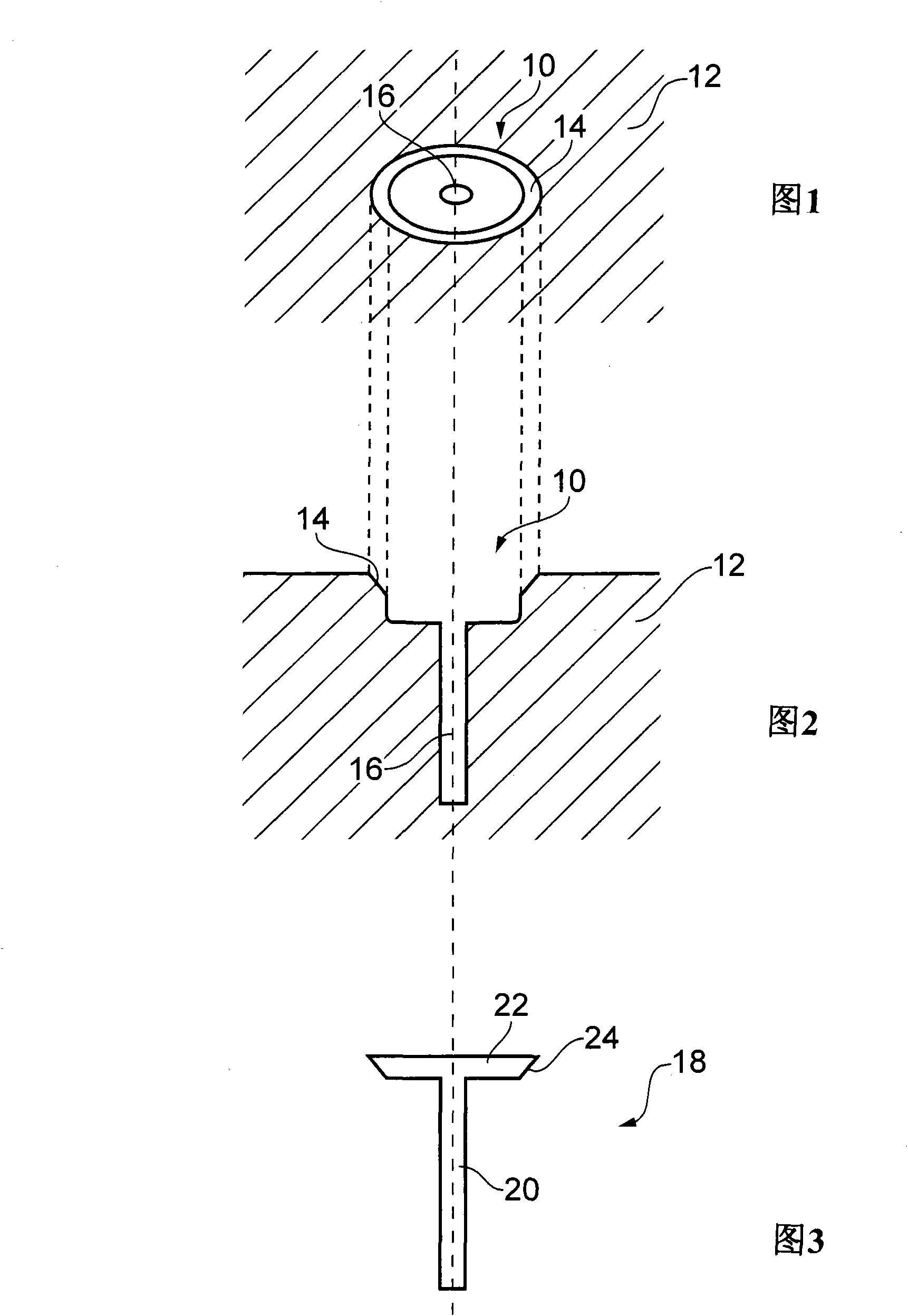
[0048] figure 1 and figure 2 A perspective view and a cross-sectional view of the valve seat are shown, respectively. image 3 A side view of the valve disc for insertion into the valve seat is shown. These valves are of the type found, for example, in the cylinder heads of automobile engines.

[0049] The valve seat 10 is positioned in the valve body 12 . The valve seat includes a conical surface 14 defining a recess in the valve body which opens into a cylindrical bore 16 . The valve disc 18 includes a cylindrical stem 20 sized to fit snugly in the cylindrical bore of the valve seat. At one end of the cylindrical rod 20 is provided a disc member 22 having a conical surface 24 on its peripheral surface. The disc members of the valve seat and the valve disc have corresponding conical surfaces 14 and 24 which form a seal when the valve disc is inserted into the valve seat.

[0050] For the valve to work well, there needs to be a good fit between the seat and the conical su...


PUM


Abstract

A method of determining the dimensions and location of a surface feature, for example a valve seat. The surface of the feature is measured, for example using a spiral scan path with a tactile probe and the multiple data points acquired from the scan are used to create a digitized image. The digitized image is fitted to a nominal image (e.g. CAD data) of the surface feature. The deviation of the digitized image from the nominal image is used to determine at least one of the dimensions, location and form deviation of the surface feature.

Description

technical field [0001] The present invention relates to a device and a method for measuring surface characteristics, in particular by forming a digitized image of said surface. The invention also relates to a method of adaptive scanning using an articulating probe capable of orienting a surface sensing device about two or more axes mounted on a coordinate positioning machine that Examples are coordinate measuring machines (CMMs), machine tools, articulating arms, and the like. Background technique [0002] According to conventional practice, after a workpiece is manufactured, it is inspected on a coordinate measuring machine (CMM), which has axes capable of three orthogonal coordinates in X, Y, and Z within the workspace of the machine tool. direction is driven. The shaft may carry a measuring probe which generates a signal upon detection of the surface of the workpiece being inspected, for example by contact between the stylus of the measuring probe and the surface. [0...

Claims


Application Information

Patent Timeline
Patent Type & Authority Applications(China)
IPC IPC(8): G01B21/04G01B5/008G01B5/00G01B5/20
CPCG01B5/0032G01B5/012G01B21/045
Inventor 哈立德·马穆尔琼·路易斯·格热西亚克
Owner RENISHAW PLC
Why Eureka
Try Eureka