
Rolling control device and rolling control method

A technology of control device and control method, applied in contour control, temperature control, length measuring device, etc., can solve problems such as poor shape, and achieve the effect of improving quality and shape quality

Active Publication Date: 2007-03-14
HITACHI LTD
View PDF2 Cites 8 Cited by
  • Summary
  • Abstract
  • Description
  • Claims
  • Application Information

AI Technical Summary

Problems solved by technology

Furthermore, the shape of the rolled material to be rolled is a factor that determines product quality, etc., and its shape failure causes cracks and warps, etc., and is also greatly related to production stability.

Method used


Image

  • Rolling control device and rolling control method
  • Rolling control device and rolling control method
  • Rolling control device and rolling control method

Examples


no. 1 Embodiment approach

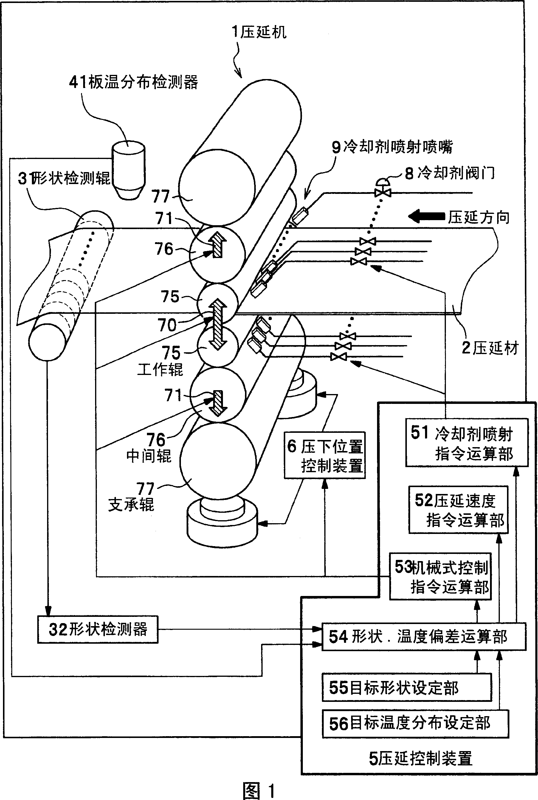
[0028] Hereinafter, a first embodiment of the present invention will be described in appropriate detail with reference to FIGS. 1 to 5 . Fig. 1 shows a schematic configuration example of a rolling machine to which the rolling control device of the present invention is applied. As shown in FIG. 1 , the calender rolls of the calender 1 are 6-stage calender rolls composed of work rolls 75 , intermediate rolls 76 and backup rolls 77 .

[0029] On the inlet side of the calender 1, a plurality of coolant injection nozzles 9 for injecting coolant to the work rolls 75 and the rolled material 2 are provided along the work rolls 75 in the sheet width direction. These coolant injection nozzles 9 have a structure that can individually control ON / OFF of coolant injection by controlling the opening and closing of the coolant valve 8 , or control the injection amount of the injected coolant.

[0030]In addition, on the exit side of the calender 1, a shape detecting roll 31 and a shape detec...

no. 2 Embodiment approach

[0087]Next, a second embodiment of the present invention will be described with reference to FIGS. 6 to 9 . Fig. 6 is a schematic diagram showing a configuration example of functional blocks of a rolling control device in a second embodiment.

[0088] As shown in FIG. 6, the rolling control device 5a in the second embodiment is constituted by a computer equipped with a CPU and a memory on the hardware side, and has a target shape setting unit 55 and a target temperature division setting unit 56 in terms of functions. , the shape and temperature deviation calculation unit 54, the coolant injection command calculation unit 51a and other functional blocks constituted. The only difference from the first embodiment is the coolant injection command calculation unit 51a. Moreover, the structure (refer FIG. 1) of the rolling machine 1 using the rolling control apparatus 5a is also the same as that of 1st Embodiment. Hereinafter, the same components as those in the first embodiment a...


PUM


Abstract

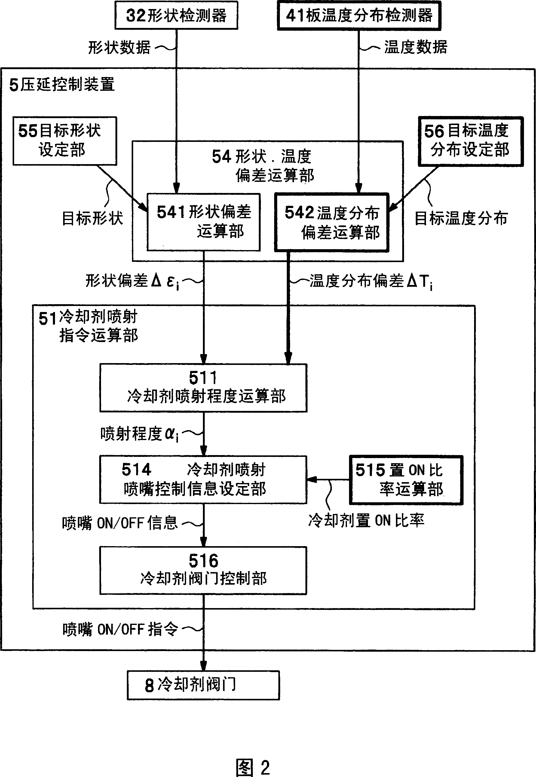
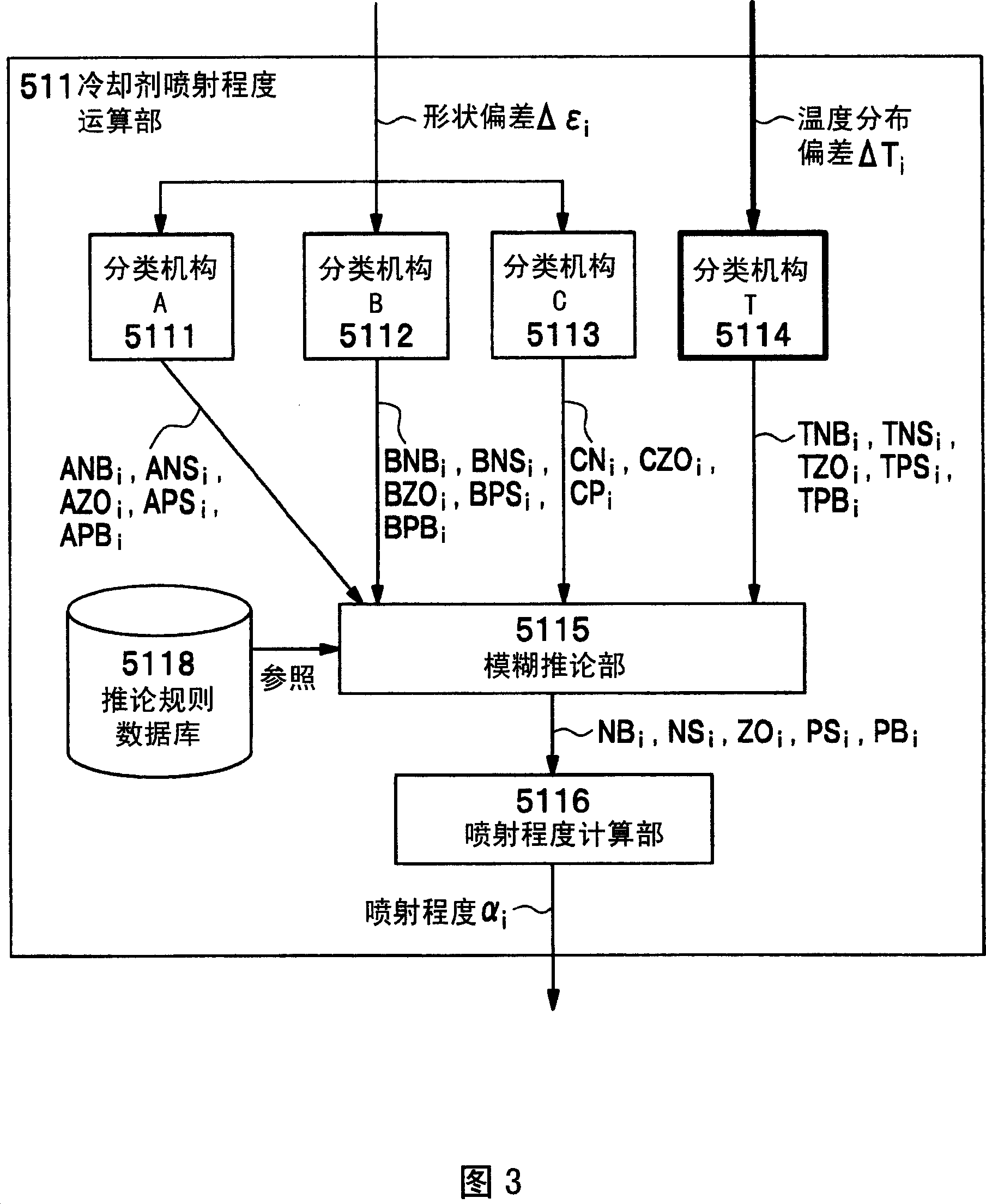
The invention is to improve magnetic characteristics and shape quality by simultaneously controlling both of strip temperature and temperature distribution in a width direction of a rolling material and strip shape of the rolling material. A coolant jet command computation unit (51) calculates a widthwise deviation of shape of the rolling material (2) detected by a shape detector (32), and widthwise deviation of temperature distribution of the rolling material detected by a strip temperature distribution detector (41) and obtains a widthwise distribution of coolant jetting level which is a necessary level for coolant jetted from a coolant jet nozzles (9). Then, based on the obtained widthwise distribution of coolant jetting level, control information for the coolant jetting nozzle (9) to jet the coolant is set up, and based on the control information set up, an ON / OFF command for coolant jetting is issued to coolant valves (8).

Description

technical field [0001] The present invention relates to a rolling control device and a rolling control method of a rolling machine for rolling a rolled plate-shaped rolling material by controlling the plate shape and temperature distribution in the vicinity of work rolls. Background technique [0002] In conventional calenders, a shape detector installed on the exit side of the calender is used to measure the shape of the rolled material. Based on the detection result, the curvature of the work rolls can be changed by bending the rolls. The gap difference (leveling: leveling) is used to control the shape of the rolled sheet. At this time, the left and right symmetrical components of the plate shape are controlled by the rollers, and the left and right asymmetric shapes are corrected by the leveling. [0003] In addition, cooling agents such as rolling oil (coolant) and water are sprayed to the work rolls, so that local elongation and local shape defects of the rolled materi...

Claims


Application Information

Patent Timeline
IPC IPC(8): B21B37/32B21B37/74
CPCB21B37/32B21B37/74B21B38/006B21B38/06B21B38/08
Inventor 福地裕服部哲
Owner HITACHI LTD
Learn More