Double headstock bed type milling machine

A double-spindle and spindle box technology, which is applied in the field of milling machines, can solve the problems of inability to process parts on both sides at the same time and low processing efficiency, and achieve the effect of wide processing range and improved work efficiency

Inactive Publication Date: 2010-03-17
SHANDONG WINNER CNC MACHINE
View PDF0 Cites 12 Cited by
  • Summary
  • Abstract
  • Description
  • Claims
  • Application Information

AI Technical Summary

Problems solved by technology

The disadvantage of this structure is that the milling machine can only install one spindle box vertically or hor

Method used


Image

  • Double headstock bed type milling machine
  • Double headstock bed type milling machine
  • Double headstock bed type milling machine

Examples


Embodiment Construction

[0009] Below in conjunction with accompanying drawing and specific embodiment the present invention is described in further detail:

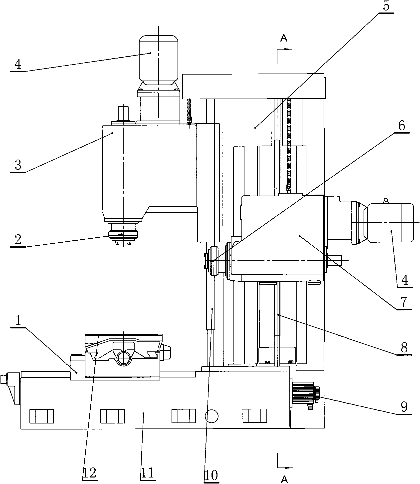
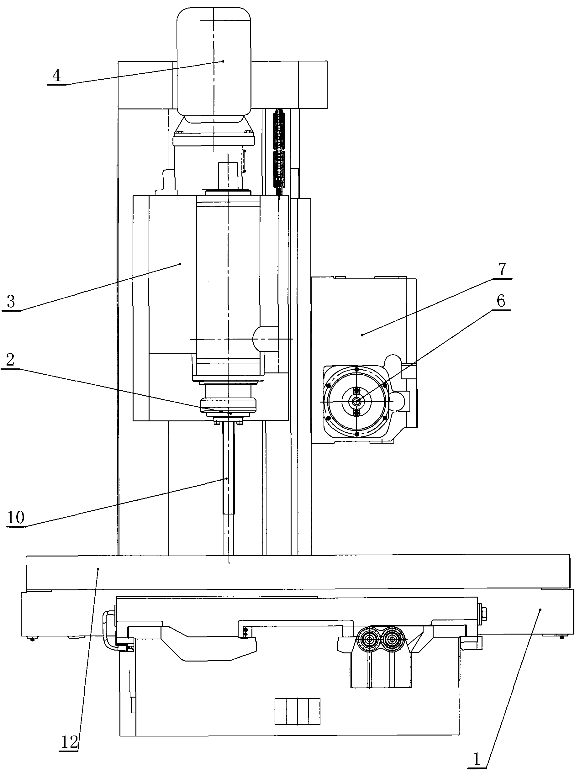
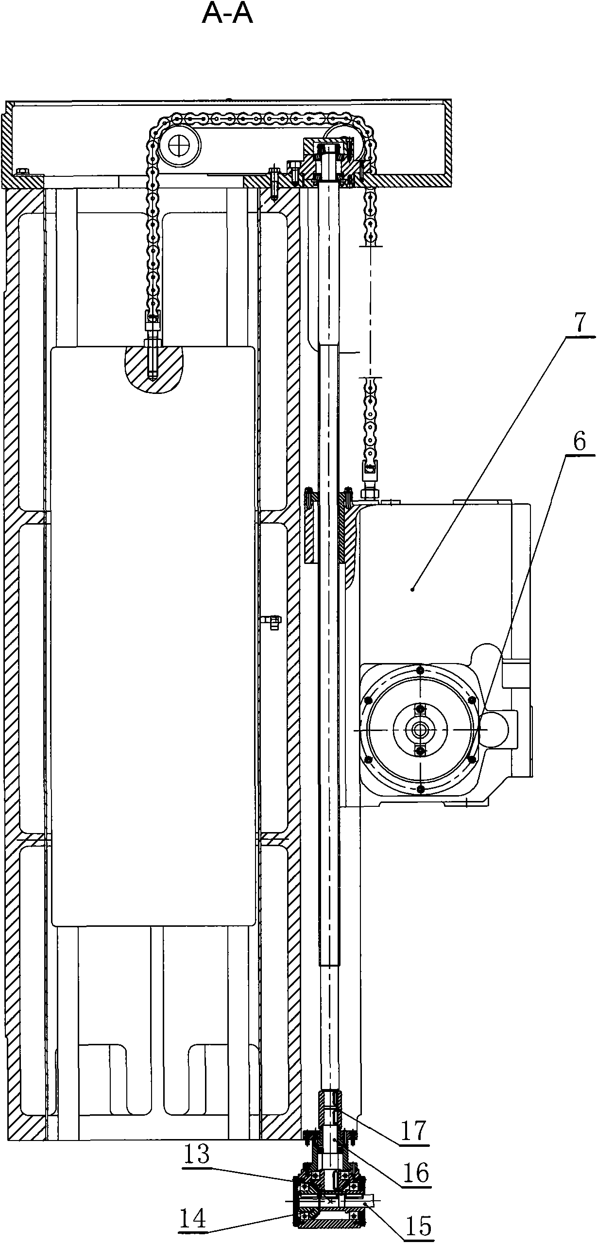
[0010] A double headstock bed milling machine such as figure 1 , 2 , 3, including a base 11, a slider 1 is designed on the upper surface of the base 11, a workbench 12 is installed on the slider 1, the slider 1 and the base 11 are relatively slidingly connected, and the rear part of the base 11 is designed with a column 5, and the column 5 Guide rails are fixedly installed on the surface, and it is characterized in that: the front and side surfaces of the column 5 are respectively connected with an end milling device and a horizontal milling device. In this embodiment, the end milling processing device includes an end milling headstock 3, a power motor 4 is installed on the end milling headstock 3, an end milling spindle unit 2 is installed in the end milling headstock 3, and the end milling spindle unit 2 is The parts are connected with the p...


PUM


Abstract

The invention relates to a double headstock bed type milling machine which has a double headstock structure and high machining efficiency, can simultaneously finish double-sided machining of parts. The double headstock bed type milling machine comprises a pedestal, wherein a slide block is designed on the surface on the pedestal, a worktable is installed on the slide block, the slide block and thepedestal are in relative slip connection, an upright post is designed at the rear part of the pedestal, a guiding rail is fixedly installed on the surface of the upright post, and an end milling machining device and a horizontal milling machining device are respectively connected with the front surface and the lateral surface of the upright post.

Description

technical field [0001] The invention relates to a milling machine, in particular to a double spindle box bed type milling machine. Background technique [0002] At present, the known bed-type milling machine is composed of a column, a single spindle box vertically or horizontally, a lifting screw pair, and a power input mechanism. The feed power source placed on the top or bottom of the column transmits power to the lifting screw pair through the belt or gear, and the lifting screw pair drives the single headstock to move up and down along the column vertically or horizontally. The disadvantage of this structure is that the milling machine can only be installed with one spindle box vertically or horizontally, the processing efficiency is low, and the two sides of the parts cannot be processed at the same time. Contents of the invention [0003] In order to overcome the shortcomings of the existing traditional structure, the object of the present invention is to provide a ...

Claims


Application Information

Patent Timeline
IPC IPC(8): B23C1/10B23C9/00
Inventor 秦瑶许慎杰谭英民杜恒志孙晋煜刘进才褚宏旭
Owner SHANDONG WINNER CNC MACHINE
Why Eureka
Try Eureka