Movable spanner

An adjustable wrench and wrench technology, applied in the field of connection, disassembly or clamping tools and fastening, can solve the problems of increasing material, affecting the accuracy of clamping gap, shaking of movable jaws, etc., to achieve reasonable stress conditions and extended use. The effect of high life and high clamping accuracy

Inactive Publication Date: 2010-03-17
鲁宏
View PDF0 Cites 17 Cited by
  • Summary
  • Abstract
  • Description
  • Claims
  • Application Information

AI Technical Summary

Problems solved by technology

[0003] At present, the cross-sectional shape of the sliding groove on the fixed jaw is generally a round hole. When the nut is tightened by twisting the wrench, the workpiece will generate a reaction force on the inner surface of the sliding groove on the fixed jaw. After decomposing the force, its horizontal direction The component force of the sliding groove will produce an outward thrust on the inner surface of the sliding groove, and the thrust will make the sliding groove open to both sides. After a period of use, a gap will be generated between the movable jaw and the fixed jaw, causing the adjustable wrench When moving, the movable jaw shakes, which affects the accuracy of the clamping gap, resulting in a decrease in the clamping torque. The user needs to constantly readjust the clamping gap to adapt to the size of the clamped workpiece, which causes a lot of inconvenience to the user. Long-term When using or applying a large force, it may even cause deformation of the fixed jaw, reducing the service life of the adjustable wrench
At present, in order to overcome the above defects, the general method is to thicken the two side walls of the sliding groove, but this method cannot fundamentally eliminate the gap, and increases the materials used to manufacture the wrench, which increases the manufacturing cost

Method used


Image

  • Movable spanner
  • Movable spanner
  • Movable spanner

Examples


Embodiment 1

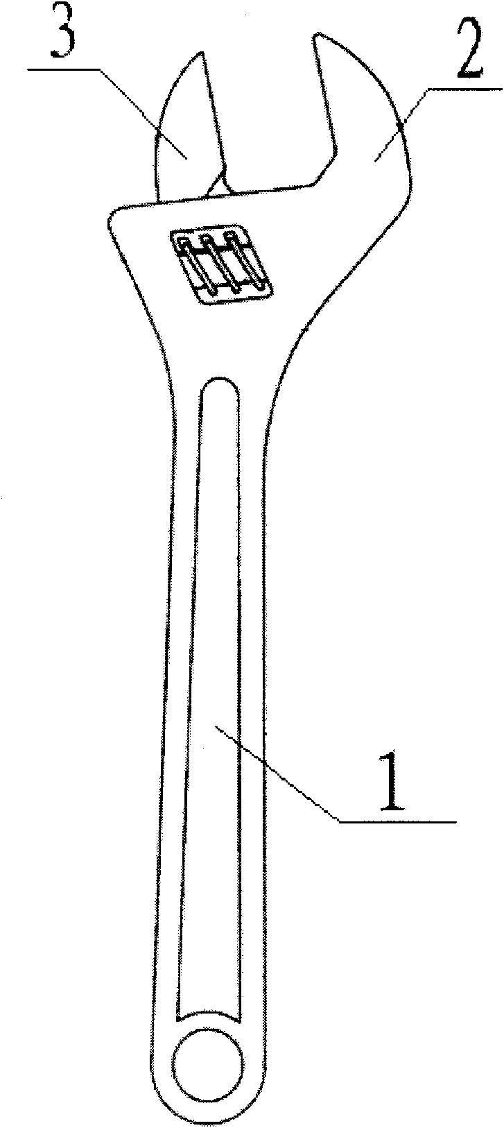
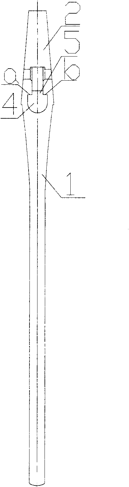
[0018] As shown in the figure, the movable wrench includes a wrench body 1, a fixed jaw 2 and a movable jaw 3. The front end of the wrench body 1 is provided with a fixed jaw 2, and the fixed jaw 2 is provided with a sliding groove 4 adjacent to it. The slide rail 5, the moving column 6 integrated with it is arranged axially under the movable jaw 3, and the moving column 6 is embedded in the sliding groove 4 and the slide rail 5. The inner surfaces a and b of the slide groove 4 adjacent to the slide rail 5 are horizontal, and the corresponding outer surfaces c and d of the moving column 6 are also horizontal. When the wrench is working, the force acting on the inner surface of the sliding groove 4 is the force perpendicular to the a surface and the b surface, that is, the vertical force. This force has no component force in the horizontal direction, so the fixed jaw 2 and the movable jaw 3 can be eliminated. The gap between the adjustable wrench will not cause the movable jaw ...

Embodiment 2

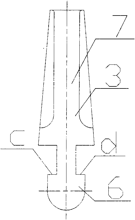
[0022] Such as Figure 4 and Figure 5 As shown, the inner surfaces a and b of the sliding groove 4 adjacent to the slide rail 5 are an inclined plane, and the cross-sectional shape of the plane is shown in the figure, which is up high and down low. The c-plane and d-surface of the corresponding outer surface of the moving column 6 are also inclined planes, and their cross-sectional shapes are correspondingly up-up and down-down. When the wrench is working, the force acting on the inner surface of the sliding groove 4 is shown in the figure, and the component force of the force in the horizontal direction points to the groove, so it will not generate an outward thrust on the sliding groove 4, eliminating the need for fixing clamps. The gap between mouth 2 and movable jaw 3.

[0023] Others are the same as embodiment 1.


PUM


Abstract

The invention relates to a movable spanner, and belongs to the field of fastening, connecting, detaching or clamping tools. The movable spanner overcomes the defects of the prior movable spanner thatthe section of the slide groove is a round hole, so the movable nip and the fixed nip of the movable spanner during use are easy to form swaying clearance to make the movable nip sway and reduce clamping precision. The movable spanner comprises a fixed nip at the front end of the spanner body and a movable nip matched with the fixed nip, wherein a movable pole is axially and integrally arranged under the movable nip; the movable pole is embedded into a slide chute of the fixed nip and a slide rail nearby the slide chute; and the inner surface of the slide chute nearby the slide rail is planar,and the outer surface of the movable pole contacted with the inner surface has a corresponding shape. When in use, the movable spanner can bear reasonable force to eliminate the swaying clearance between the movable nip and the fixed nip, thereby preventing the movable nip from swaying in spanning and improving the clamping precision.

Description

technical field [0001] The invention relates to a tool for fastening, connecting, disassembling or clamping, in particular a novel adjustable wrench. Background technique [0002] Adjustable wrench is widely used in various machining fields and daily life because of its adjustable clamping gap and convenient use. At present, the commonly used wrench is composed of movable jaws, fixed jaws, and adjusting nuts. The movable jaws are installed in the sliding groove of the fixed jaws. Close or open to adjust the jaw size. When in use, the wrench clamps the workpiece. After pulling a certain angle, loosen the movable jaw, change a position on the workpiece, and then turn the adjusting nut to adjust the clamping gap, so that the movable jaw can clamp the workpiece again and continue to twist. Wrench for final tightening of the workpiece. [0003] At present, the cross-sectional shape of the sliding groove on the fixed jaw is generally a round hole. When the nut is tightened by t...

Claims


Application Information

Patent Timeline
Patent Type & Authority Applications(China)
IPC IPC(8): B25B13/12
Inventor 鲁宏
Owner 鲁宏
Why Eureka
Try Eureka