
Ratchet wrench

A technology of ratchet wrench and ratchet parts, which is applied in the field of wrenches, which can solve problems such as reduced service life, obstruction of steel ball movement, and loss of function of ratchet wrench, so as to achieve the effects of improving service life, simplifying processing procedures, and saving processing costs

Active Publication Date: 2012-07-04
胡厚飞
View PDF2 Cites 0 Cited by
  • Summary
  • Abstract
  • Description
  • Claims
  • Application Information

AI Technical Summary

Problems solved by technology

[0005] Although it has three housings, compared with the No. 7146883 patent, the specific implementation of the No. 6981434 patent is indeed easier to process, and the reversing effect of its double card catch is more reliable than the former, but it still has There are a few missing points. The bumps of the double-clip levers are moved by the toggle button, but there are still some problems that the bumps are easy to slip off from the toggle button, or the toggle button cannot be linked with the bumps of the snap pieces. Furthermore, the wrench body Because the surface provides storage for the knob, and a steel ball is required under the knob, the volume of the head of the wrench body cannot be effectively reduced
[0006] In addition, the above-mentioned patents all use steel balls to cooperate with springs to achieve the effect of jacking. When the spring fails after a long time of use, or the spring is twisted when it is toggled, the ratchet wrench will lose its function. Therefore, how to replace the spring is also the present invention. Desperate for improvement
[0007] Moreover, the steel ball is pushed by the spring to make the steel ball repeatedly move back and forth in the groove, which will easily reduce the service life and cause the problem of poor positioning effect, so there is still a need for improvement
[0008] Furthermore, the reciprocating movement of the steel ball and the spring in the groove must be based on a good moving path, but the moving path of the steel ball in the groove is a limited design, so once the steel ball and the groove encounter water, it will cause rust Or when encountering impurities, it is easy to form obstacles to the movement of the steel ball, which will cause the wrench to lose its positioning effect, so there is still a need for improvement

Method used


Image

  • Ratchet wrench
  • Ratchet wrench
  • Ratchet wrench

Examples


Embodiment Construction

[0032] Regarding the technology, means and effects used in the present invention, a preferred embodiment is given and described in detail below with drawings, which are for illustration purposes only, and are not limited by this structure in the patent application.

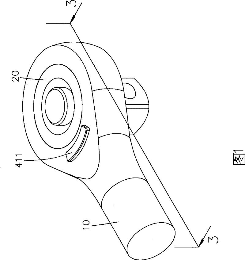
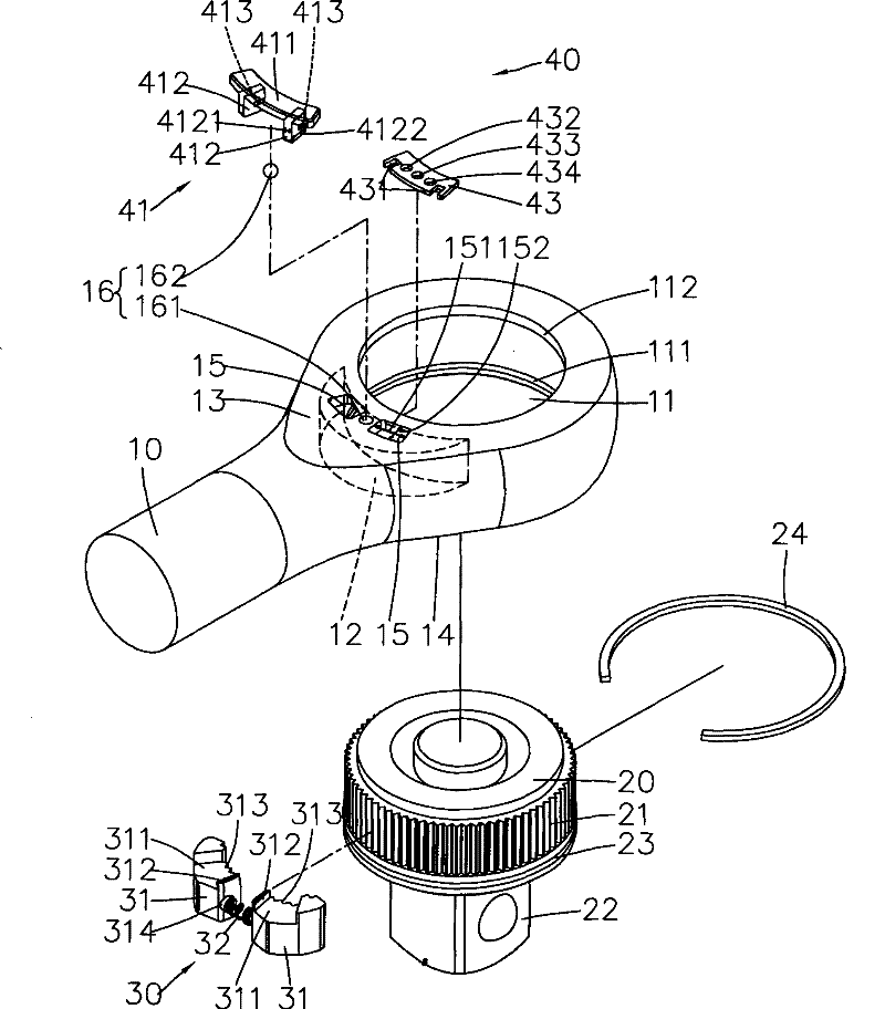
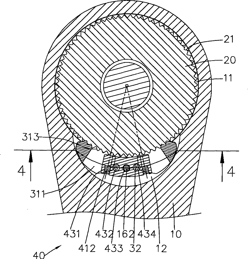
[0033] refer to figure 1 and figure 2 , is a three-dimensional appearance view and a three-dimensional exploded view of the ratchet wrench of the present invention. The ratchet wrench of the present invention includes a body 10 , a ratchet component 20 , a locking device 30 and a reversing switch 40 .

[0034] The body 10 is provided with a circular first accommodating space 11, and the inner wall of the first accommodating space 11 is provided with an arc-shaped second accommodating space 12, the second accommodating space 12 communicates with the first accommodating space 11 . The body 10 has opposite first side 13 and second side 14, the first accommodating space 11 penetrates the two sides 13, 14 of the bo...


PUM


Abstract

The invention relates to a ratchet wrench, which comprises a body, wherein the body is provided with two accommodating spaces which accommodate a ratchet piece, a clamping device and a transfer switch respectively; the clamping device comprises two clamping pieces and an elastic piece; the two clamping pieces are selectively meshed with the ratchet piece; the elastic piece is connected with the two clamping pieces; an accommodating part is formed on the surfaces of the two clamping pieces respectively; the transfer switch comprises a toggle; the toggle comprises a toggle part and two feet; the two feet extend into the second accommodating space and are positioned at the accommodating parts of the two clamping piece; and the toggle part is toggled to make the two feet selectively pull the clamping pieces and make teeth of the clamping pieces selectively far away from teeth of the ratchet piece. The ratchet wrench achieves the purpose of saving processing cost by the double accommodating spaces, and utilizes the two feet of the toggle to reliably pull the clamping pieces, so that the clamping pieces avoid separation or slipping.

Description

technical field [0001] The invention relates to a wrench, which refers to a ratchet wrench which is easy to process and can reverse direction, especially a ratchet wrench which uses arc swing to control the direction change. Background technique [0002] Common reversing ratchet wrench such as No. 7146883 of U.S. Patent No. figure 2 As disclosed, the wrench body 10 has three housings 110, 111, 113, and the housings 110, 111, 113 are respectively equipped with a ratchet 20, a locking member 30 and a jacking device 50. The switch 60 further controls the locking member 30 to pivotally engage with the ratchet 20 . [0003] This kind of design that must process three parts makes it difficult to effectively reduce the processing cost of the wrench body. In particular, the part for accommodating the jacking device is coaxial with the wrench body, which is difficult to process. In addition, The above-mentioned single locking member has hidden dangers of inaccurate commutation, whi...

Claims


Application Information

Patent Timeline
Patent Type & Authority Patents(China)
IPC IPC(8): B25B13/46B25B23/00
Inventor 胡厚飞
Owner 胡厚飞
Learn More