Device for detecting position of print head and printer provided with same

A detection device and print head technology, applied in power transmission devices, printing, transfer materials, etc., can solve the problems of large installation space, no contact, and failure to print normally, and achieve the effect of low equipment cost and small installation space

Active Publication Date: 2010-03-17
SHANDONG NEW BEIYANG INFORMATION TECH CO LTD
View PDF0 Cites 10 Cited by
  • Summary
  • Abstract
  • Description
  • Claims
  • Application Information

AI Technical Summary

Problems solved by technology

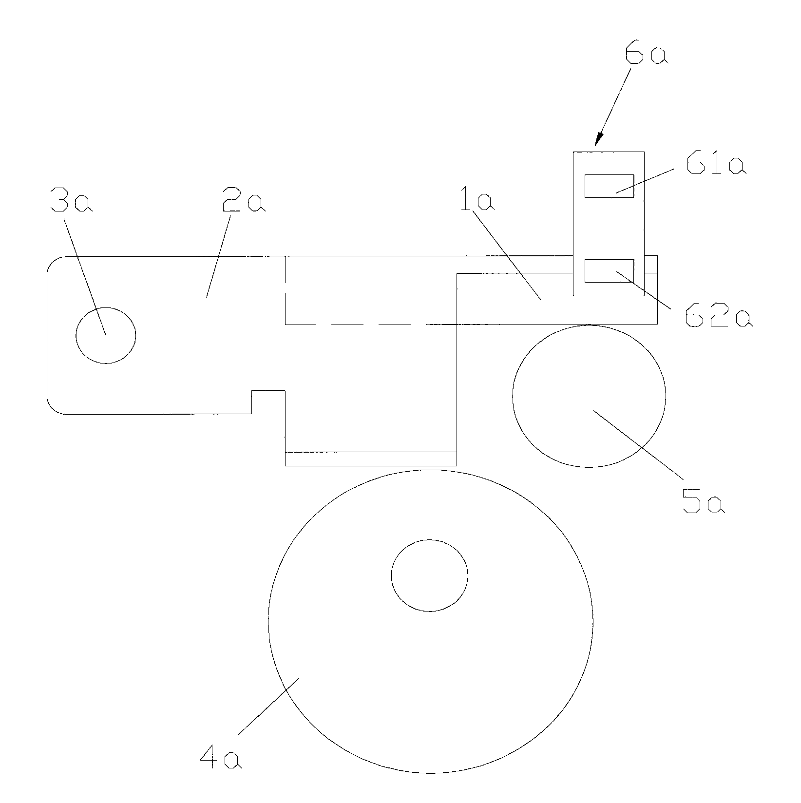
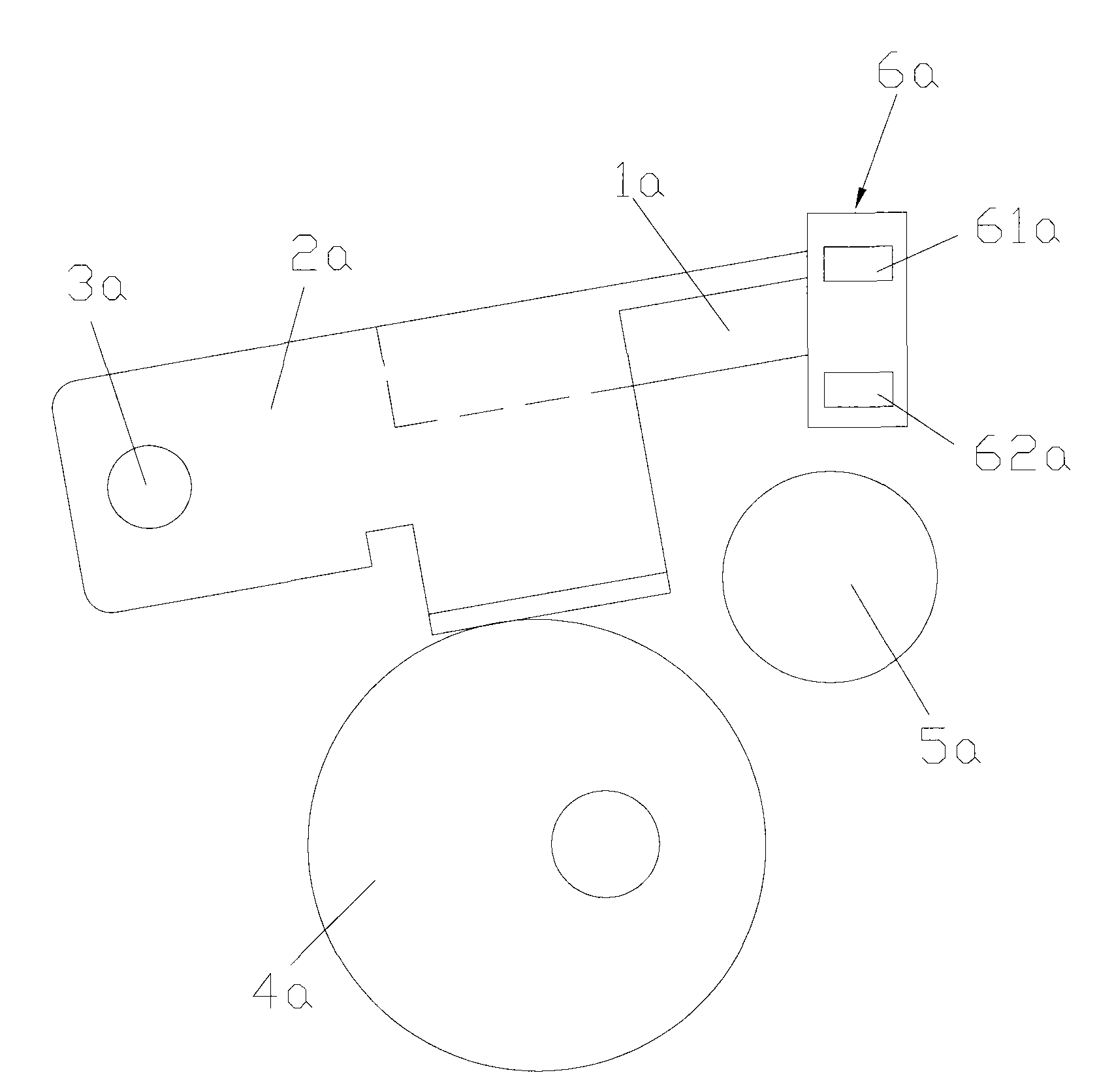
[0009] In summary, since the print head position detection device 6a judges the position of the print head 1a through the first sensor 61a and the second sensor 62a, since the sensitive areas of the first sensor 61a and the second sensor 62a are a range value, it cannot Accurate to a certain point value, so it is impossible to accurately control the lifting or pressing position of the printing head 1a, which can cause the printing head 1a to come into direct contact with the rubber roller 2a after the printer finishes printing, resulting in damage to the printing head 1a, or When the printer is printing, there is no contact between the print head 1a and the rubber roller 5a, and it cannot print normally
[0010] In addition, the print head position detection device 6a uses two sensors to judge the position of the print head 1a. Since there are many sensors, the installation space occupied is relatively large, and the manufacturing cost of the print head position detection device 6a is relatively high.

Method used


Image

  • Device for detecting position of print head and printer provided with same
  • Device for detecting position of print head and printer provided with same
  • Device for detecting position of print head and printer provided with same

Examples


Embodiment Construction

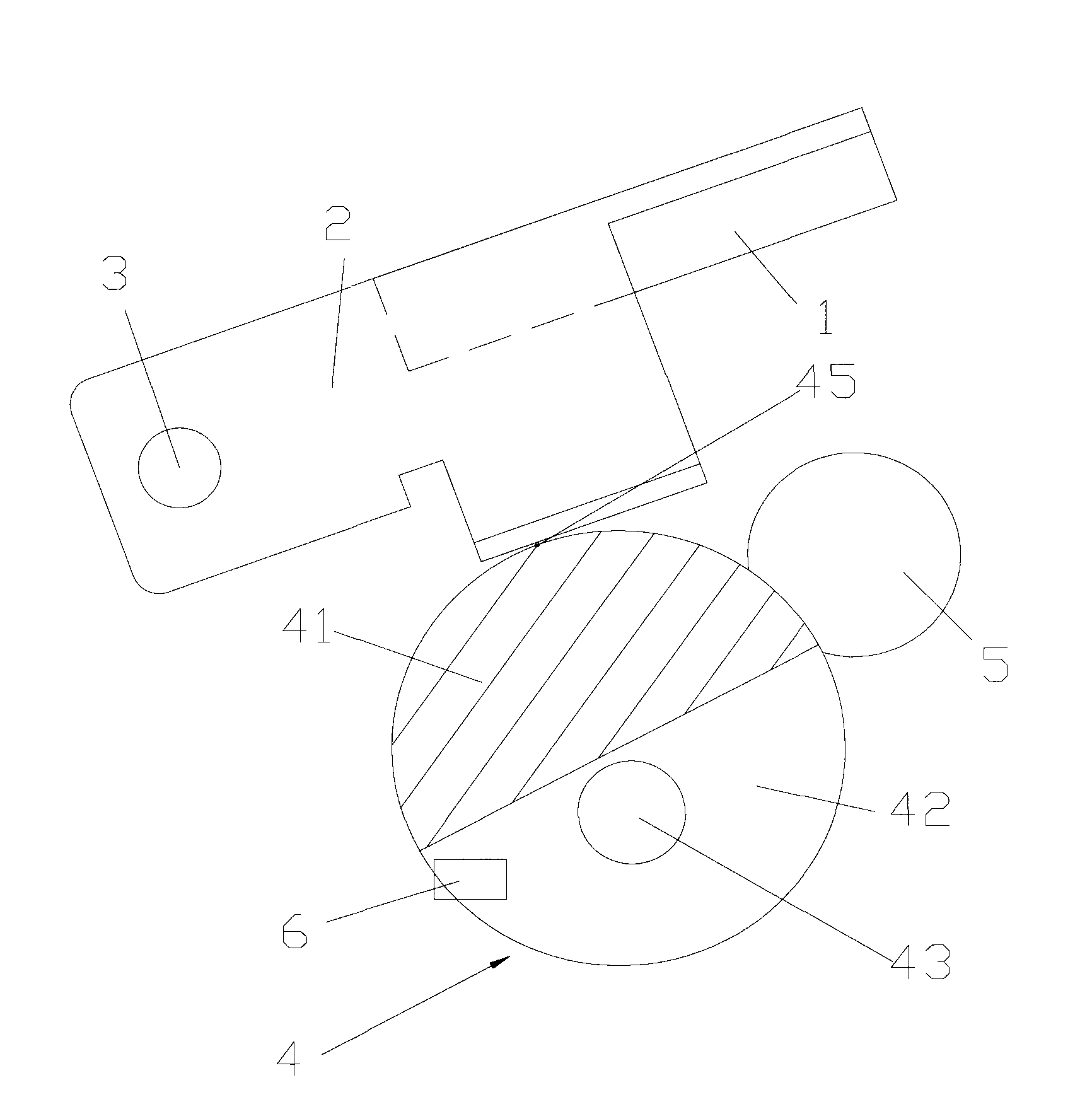
[0034] The design concept of the present invention is to control the movement of the cam by using the voltage change law of the sensor, thereby controlling the relative position of the printing head and the rubber roller.

[0035] In order to enable those skilled in the art to better understand the technical solutions of the present invention, the present invention will be further described in detail below in conjunction with the accompanying drawings and specific embodiments.

[0036] refer to image 3 and Figure 4 , image 3 It is a schematic diagram of the first embodiment of the printing head position detection device provided by the present invention under the state of the printing head being depressed; Figure 4 It is a schematic diagram of the first embodiment of the print head position detection device provided by the present invention in the state where the print head is raised;

[0037] like image 3 and Figure 4 As shown, the present embodiment provides a pri...


PUM


Abstract

The invention discloses a device for detecting the position of a print head, which is used for controlling the position of the print head of a printer. The device comprises a sensor and a cam, whereindetection areas with different reflectivity are arranged at the side of the cam, the installation position of the sensor corresponds to the detection areas at the side of the cam, and the sensor controls the position of the print head by detecting the transform of the detection areas on the cam. The sensor detects the transform among the reflection areas on the cam and sends out voltage change signals to control the print head to lift or press down. As the reflectivity of the sensor or the reflection areas can be set, the print head can be just located in the set lifting position when the voltage of the sensor comes to the failing edge, and the print head can be just located in the set press-down position when the voltage of the sensor comes to the rising edge. The device can accurately control the print head to be in a lifting position or a press-down position.

Description

technical field [0001] The invention relates to the field of printers, in particular to a print head position detection device of a thermal printer; the invention also relates to a printer with the position detection device. Background technique [0002] Generally, a thermal printer includes a printing head and a rubber roller, the printing head and the rubber roller are arranged correspondingly, and a heating element is installed on the printing head. The working principle of the thermal printer is that the heating element on the print head is heated, the rubber roller transports the thermal printing paper, and the printing head selectively heats the thermal printing paper at a certain position, thus producing corresponding graphics or text. [0003] When the thermal printer is printing, in order to ensure the normal operation of the print head, there needs to be a certain pressure between the print head and the rubber roller. Since the rubber roller has the function of su...

Claims


Application Information

Patent Timeline
Patent Type & Authority Applications(China)
IPC IPC(8): B41J2/32B41J25/308
Inventor 徐志刚谷长刚董述恂王春涛
Owner SHANDONG NEW BEIYANG INFORMATION TECH CO LTD
Why Eureka
Try Eureka