Floor washing and sucking-drying equipment

An equipment and floor washing technology, applied in cleaning equipment, carpet cleaning, floor cleaning, etc., can solve the problem that the brush plate and squeegee cannot adapt to different ground conditions, and the brush plate and squeegee cannot adapt to different ground conditions. The cleaning performance of the brush plate, the water absorption performance of the squeegee, etc., can ensure the effect of washing the floor, improve the anti-seismic effect, and optimize the space layout.

Active Publication Date: 2021-03-26
DIBANG ENVIRONMENTAL IND CO LTD
View PDF5 Cites 5 Cited by
  • Summary
  • Abstract
  • Description
  • Claims
  • Application Information

AI Technical Summary

Problems solved by technology

[0004] In the related art, the brush plate and the squeegee of the floor washing machine lack an adjustment structure, so that the brush plate and the squeegee cannot be well adapted to different ground conditions, which affects the cleaning performance of the brush plate and the water absorption

Method used


Image

  • Floor washing and sucking-drying equipment
  • Floor washing and sucking-drying equipment
  • Floor washing and sucking-drying equipment

Examples


Embodiment 1

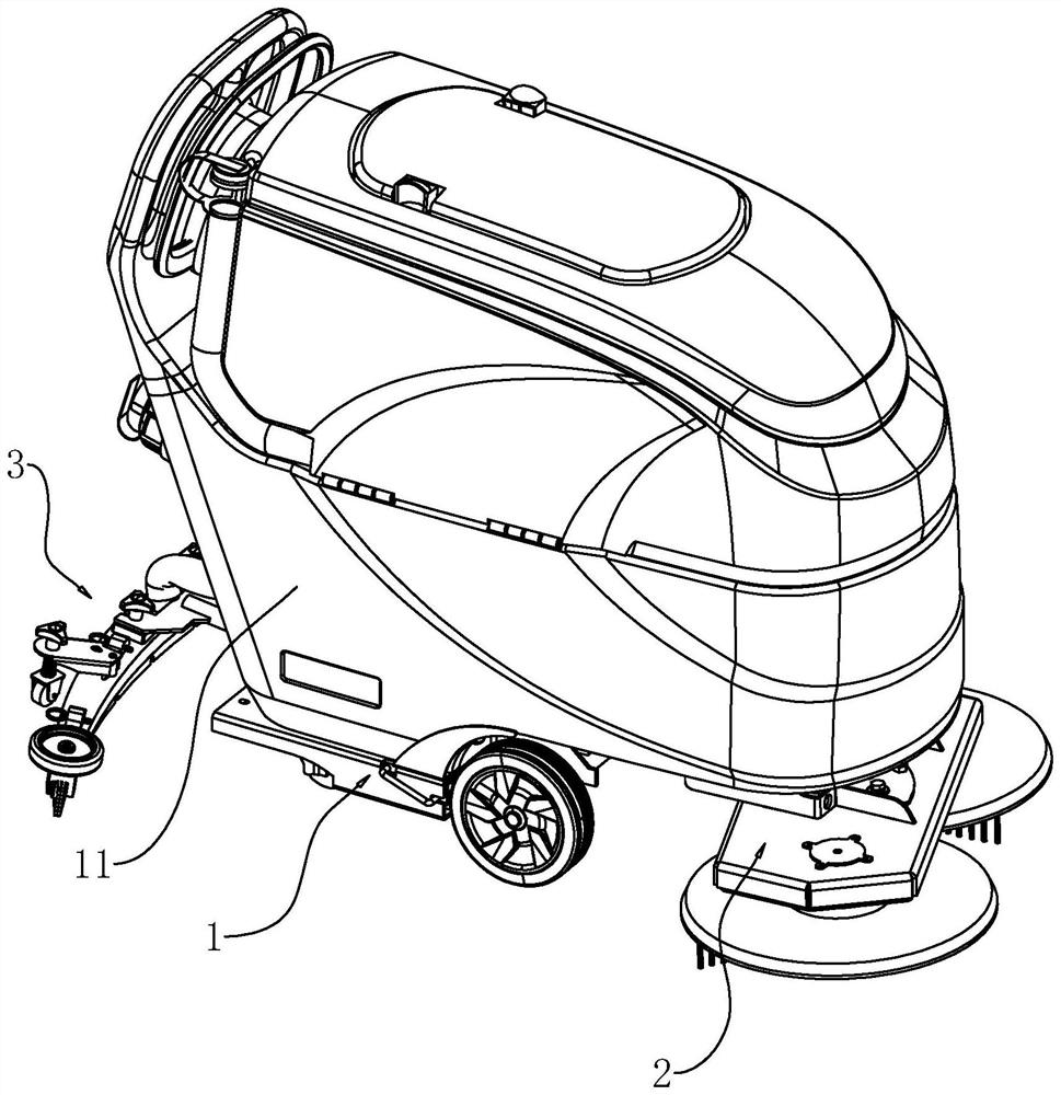
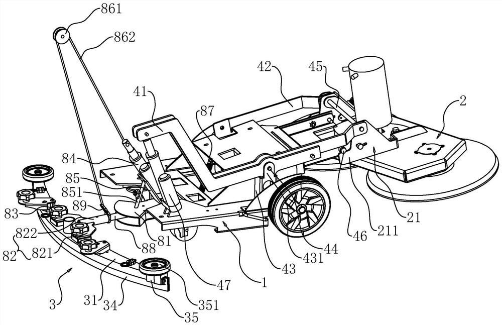
[0056] Embodiment one, with reference to figure 1 with figure 2 , the floor scrubbing and drying equipment includes frame 1, brush plate 2 and squeegee 3, frame 1 is a sheet metal part, and sheet metal has the characteristics of light weight and high strength, so frame 1 can maintain low weight For better strength, a water tank 11 is fixedly arranged on the frame 1 . refer to figure 2 The frame 1 is provided with a first lifting structure for controlling the lifting of the brush plate 2 and a second lifting structure for controlling the lifting of the squeegee 3 .

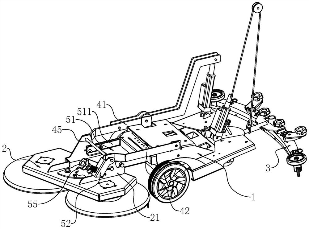
[0057] refer to figure 2 , the first lifting structure includes a swing arm group hinged on the left and right sides of the frame 1, and the rotation axes between the swing arm groups are collinear. In this embodiment, the swing arm group includes a first swing arm 41 and a second swing arm 42. The first swing arm 41 and the second swing arm 42 are also sheet metal parts, so that the first swing arm 41 and t...

Embodiment 2

[0099] Embodiment two, refer to Figure 12 The difference from Embodiment 1 is that the bottom of the water suction head 32 is provided with water guide grooves 91, and the water guide grooves 91 are respectively opened on both sides of the water suction hole 321, and the water guide grooves 91 on both sides are connected to the water suction hole 321, and the water guide grooves 91 corresponds to the shape of the water suction head 32 and extends in an arc, and the groove width of the water guide groove 91 gradually decreases from the end close to the water suction hole 321 to the end far away from the water suction hole 321 .

[0100] The implementation principle of a floor washing and drying equipment in the embodiment of the present application is: when the water suction head 32 absorbs water, the opening of the water guide groove 91 can guide the sewage to accelerate into the water suction hole 321, so that the sewage can be easily sucked into the water suction head 32, T...

Embodiment 3

[0101] Embodiment three, refer to Figure 13The difference from the first embodiment is that the grill seat 31 is protrudingly provided with a bump 921, and the interior of the bump 921 is hollow, and the grill seat 31 is provided with a mounting hole 922, and the mounting hole 922 runs through the grill seat 31 and communicates with the interior of the bump 921 , the suction head 32 is provided with a mounting block 923, the mounting block 923 can penetrate into the protrusion 921 through the mounting hole 922, the mounting block 923 and the protrusion 921 are fixed by a spring pin 93, and one end of the spring pin 93 is connected with a first pull Ring 931 , the first pull ring 931 is convenient for people to pull out the spring latch 93 .

[0102] The implementation principle of a floor washing and drying equipment in the embodiment of the present application is: by inserting the installation block 923 of the water suction head 32 into the protrusion 921, and passing the sp...


PUM


Abstract

The invention relates to the technical field of cleaning equipment, in particular to floor washing and sucking-dry equipment which is characterized by comprising a rack, a brush disc and a water sucking rake, and the rack is provided with a first lifting structure for controlling the brush disc to ascend and descend and a second lifting structure for controlling the water sucking rake to ascend and descend; the first lifting structure comprises swing arm sets horizontally hinged to the two sides of the rack, one swing arm is provided with a first driver for controlling the swing arm sets to swing, the brush disc is connected with an installing plate set hinged to the swing arm sets, the second lifting structure comprises an installing base horizontally hinged to the rack, and the installing base is provided with a second driver and an adjusting rod. The water absorption rake is connected with a connecting piece, the adjusting rod is connected with the connecting piece, a control structure is connected between the second driver and the adjusting rod, the second driver controls the adjusting rod to swing up and down through the control structure, and according to the floor washing and sucking-dry equipment, the brush disc and the water absorption rake can adapt to different ground conditions so as to guarantee the floor washing effect of a floor washing machine.

Description

technical field [0001] The invention relates to the technical field of cleaning equipment, in particular to floor scrubbing and drying equipment. Background technique [0002] Environmental sanitation is an important factor affecting the quality of life. Therefore, with the continuous improvement of people's requirements for quality of life, the requirements for environmental sanitation are also getting higher and higher. However, the work pressure of modern people is increasing day by day. It was rescued from work, so many equipment for cleaning the ground appeared to improve environmental hygiene. Commonly used are vacuum cleaners, automatic mopping machines and floor washing machines. [0003] Among them, the floor washing machine is a cleaning machine that is used to clean the hard ground while sucking up the sewage and taking the sewage away from the site. It has the advantages of environmental protection, energy saving, and high efficiency. The floor washing machine o...

Claims


Application Information

Patent Timeline
IPC IPC(8): A47L11/30A47L11/40
CPCA47L11/305A47L11/307A47L11/4058A47L11/4069Y02B40/00
Inventor 李蕾葛新奇方俊刘艳
Owner DIBANG ENVIRONMENTAL IND CO LTD
Why Eureka
Try Eureka