Core of heat exchanger

A technology of heat exchangers and cores, applied in heat exchange equipment, lighting and heating equipment, laminated components, etc., can solve the problem of reducing cooling power and product service life, cracks, especially in places where brazing connections are more serious etc. to achieve the effects of reducing thermal stress, avoiding cracks, and reducing the impact of impact

Active Publication Date: 2010-03-17
爱克奇换热技术(太仓)有限公司
View PDF0 Cites 12 Cited by
  • Summary
  • Abstract
  • Description
  • Claims
  • Application Information

AI Technical Summary

Problems solved by technology

Heat exchangers using such traditional cores are subjected to great thermal stress loads and mechanical loads during operation, especially when the cooling medium continuously passes through the heat exchanger while the cooled medium (thermal fluid) only flows intermittently. In the case of a superheat exchanger, the hot fluid channel has been subjected to frequent temperature mutations in the hot fluid inflow area, which will cause frequent thermal expansion and contraction of the various parts of the rigid heat exchanger core formed by brazing connections, resulting in heat exchange. Cracks are generated on the core of the device, especially in the place where the brazing connection is more serious, thereby reducing the cooling power and the service life of the product

Method used


Image

  • Core of heat exchanger
  • Core of heat exchanger
  • Core of heat exchanger

Examples


Embodiment Construction

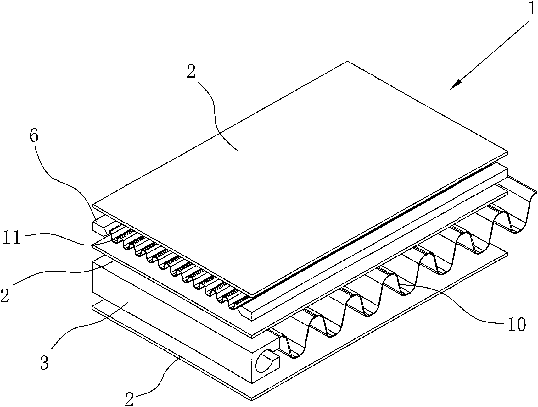
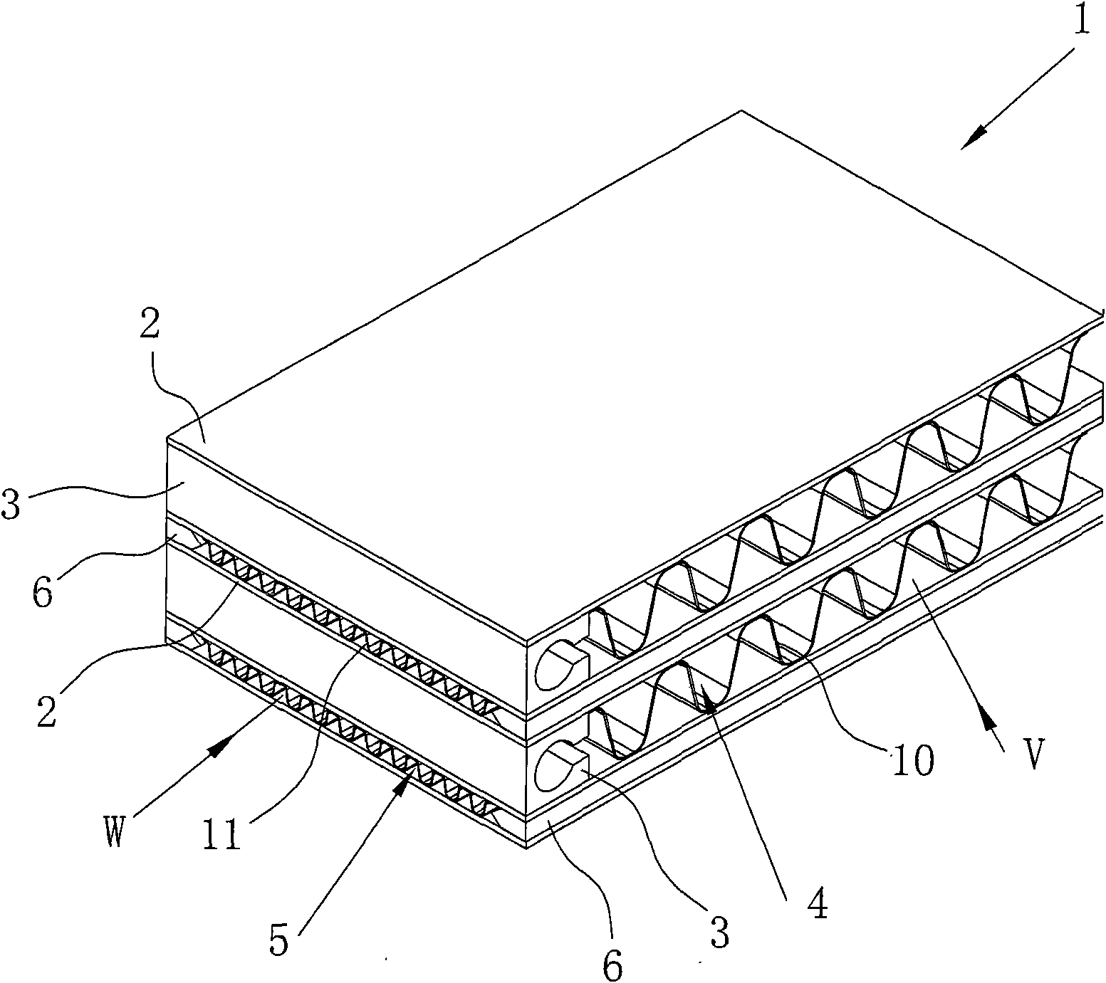
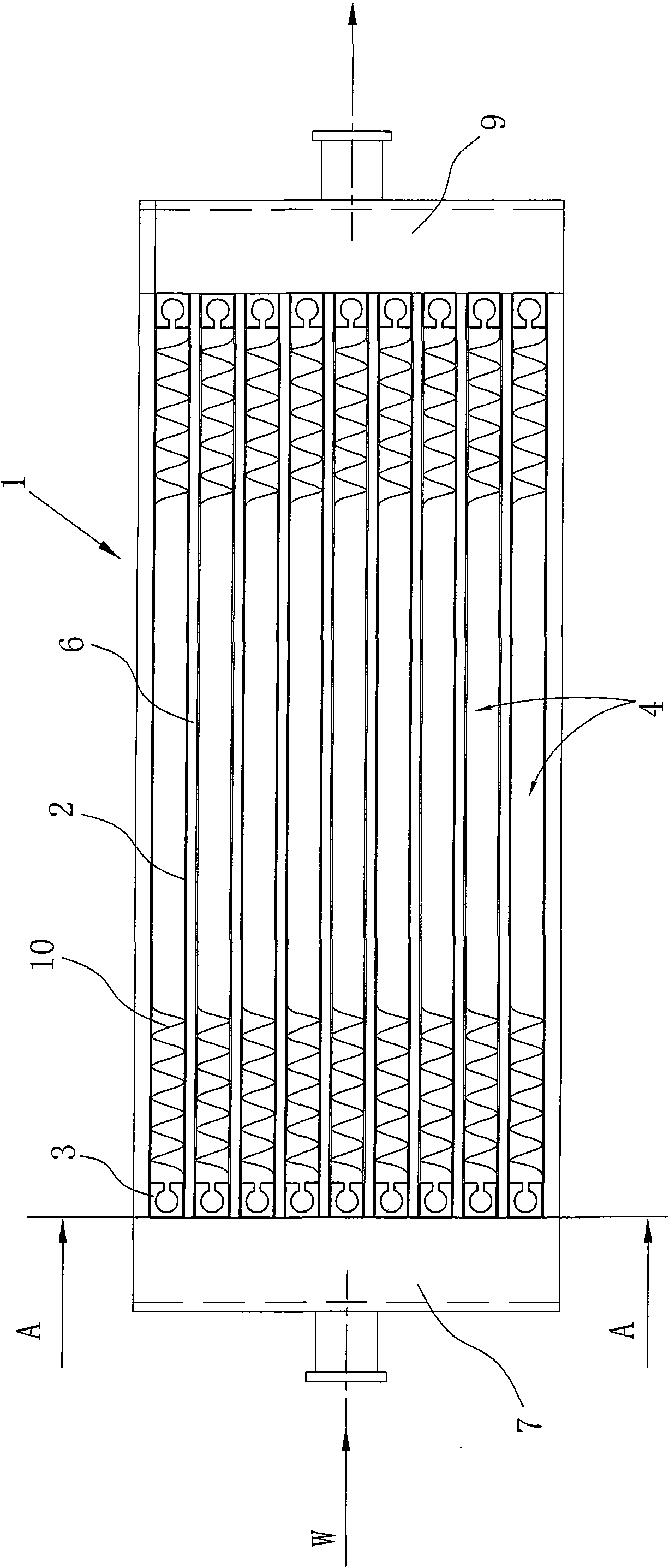
[0032] Hereinafter, embodiments of the present invention will be described with reference to attached drawings, and the parts that are the same as those in the prior art will be given the same reference symbols, and detailed description will be omitted.

[0033] See Figure 1-8 The structure diagram of a heat exchanger core 1 shown is consistent with the traditional technology in that the cold fluid passage 4 and the hot fluid passage 5 are arranged at intervals, intersecting and stacked, between the cold fluid passage 4 and the hot fluid passage 5 The rooms are separated by partitions 2. Such as Figure 2-4 As shown, the two cold fluid channel seals 3 arranged on the left and right and the two partitions 2 above and below form a front and rear cold fluid channel 4, and the two hot fluid channel seals 6 arranged at the front and back and the two spacers above and below The block partitions 2 form left and right thermal fluid passages 5 . From Figure 5 It can be seen from ...


PUM


Abstract

The invention relates to a core of a heat exchanger, comprising a cold fluid channel and a hot fluid channels. The cold fluid channel and the hot fluid channel are distributed in an overlapping way, are partitioned by partition boards and are crossed in the extension direction. The edges of the two sides of the cold fluid channel are provided with cold fluid channel seal strips. The cold fluid channel comprises the two cold fluid channel seal strips and partition boards arranged above and below the cold fluid channel seal strips; the two cold fluid channel seal strips are respectively arrangedat the inlet and the outlet of the hot fluid channel, and the cold fluid channel seal strip which is arranged at the inlet of the cold fluid channel is provided with a hole lengthwise. Because the cold fluid channel seal strip which is arranged at the inlet of the hot fluid channel is provided with the hole and is hollow, the flexibility of the hot fluid channel seal strip is improved, and the flexibility of the inlet of the whole hot fluid channel is improved accordingly. Therefore, the thermal stress impact to the core of the heat exchanger can be reduced, and the part of core of the heat exchanger, where the hot fluid flows past, can not crack due to the sudden change of temperature.

Description

technical field [0001] The invention relates to a core for a heat exchanger for cooling a high-temperature medium. Background technique [0002] In the field of industrial applications, there are many occasions that require the use of heat exchangers for cooling high-temperature media. For example, the intercooler of a vehicle engine is to cool the supercharged air exceeding 200°C through cold air or water; the air compressor is compressed The air temperature of the liquid sometimes exceeds 250°C, and it must be cooled with a heat exchanger before use; and sometimes the high-temperature liquid also needs to be cooled. [0003] The core of the traditional heat exchanger is attached Figure 14 As shown, the seal used on this traditional core is solid, and the cross-section is roughly rectangular or square. Heat exchangers using such traditional cores are subjected to great thermal stress loads and mechanical loads during operation, especially when the cooling medium continuou...

Claims


Application Information

Patent Timeline
IPC IPC(8): F28F3/08F28F3/10
Inventor 孙守荣
Owner 爱克奇换热技术(太仓)有限公司
Why Eureka
Try Eureka