
Ocean bottom seismograph placement device

A technology of throwing device and seismograph, which is applied in seismology and other directions in areas covered by water, can solve the problems of seabed seismograph damage, glass floating ball shaking, large temperature change, etc., to achieve convenient and firm installation and reduce impact. Influence, the effect of reducing the influence

Pending Publication Date: 2018-08-03
INST OF ENG MECHANICS CHINA EARTHQUAKE ADMINISTRATION
View PDF0 Cites 3 Cited by
  • Summary
  • Abstract
  • Description
  • Claims
  • Application Information

AI Technical Summary

Problems solved by technology

[0004] At present, the submarine seismograph basically places the seismic observation equipment in the deep-sea glass floating ball. After the floating ball is fixed on the sinking coupling frame, it is directly dropped from the sea to the bottom of the sea for free landing. When the submarine seismograph is in contact with seawater during the launching process, it is very easy to cause sudden violent vibration, which may directly cause damage to the submarine seismograph; When observing the seabed, the glass floating ball will inevitably shake due to the influence of the seabed ocean current, and the temperature change is relatively large, which directly leads to the accuracy of the measurement data of the precision seismic observation instrument.
[0005] In addition, developed countries such as Japan and the United States all use underwater robots to launch submarine seismometers, and the cost of launching them once is relatively expensive; in addition, the rest of the submarine seismometers are basically launched directly from the sea to the bottom of the sea for free landing

Method used


Image

  • Ocean bottom seismograph placement device
  • Ocean bottom seismograph placement device
  • Ocean bottom seismograph placement device

Examples


Embodiment Construction

[0019] Below in conjunction with accompanying drawing, the present invention is described in further detail:

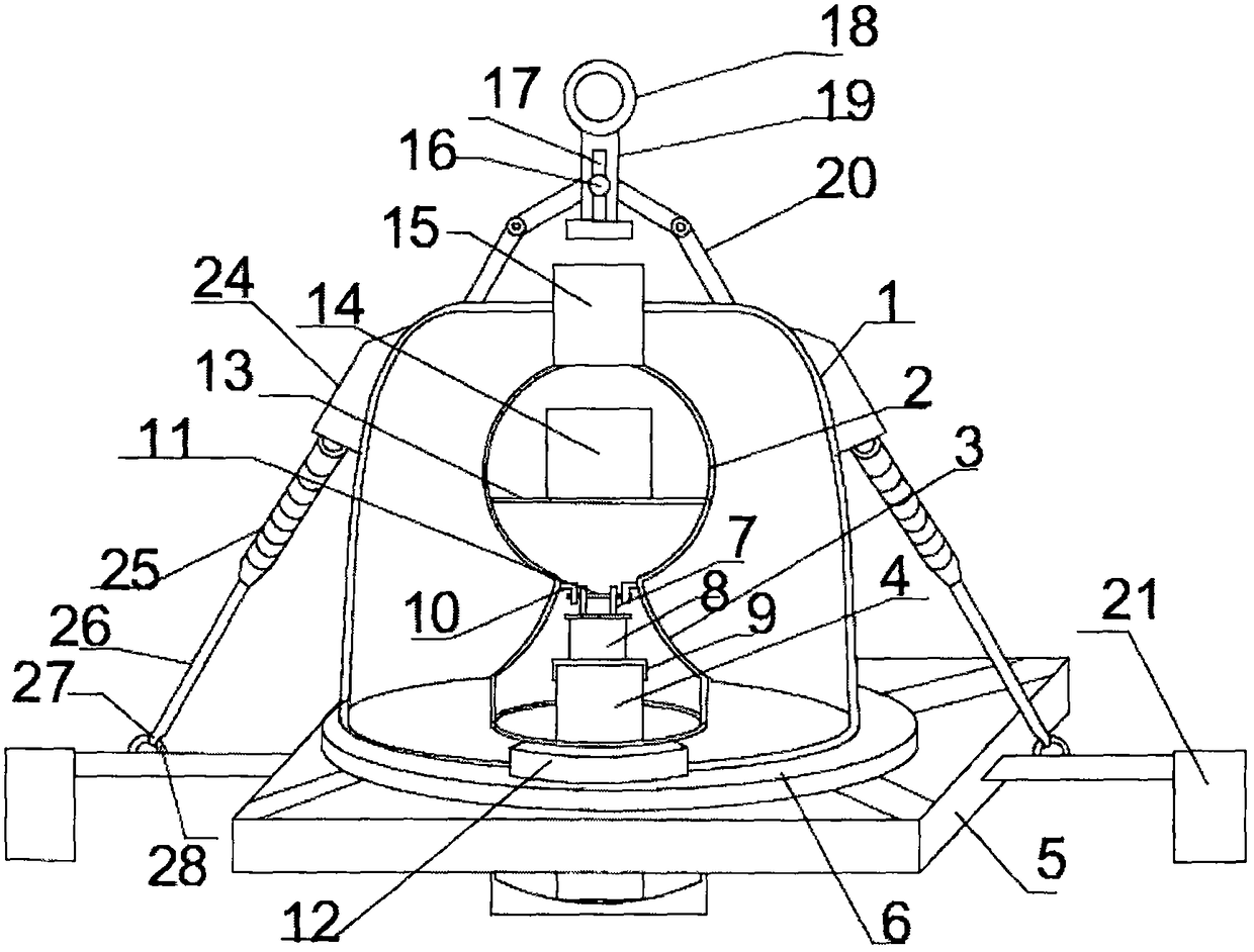
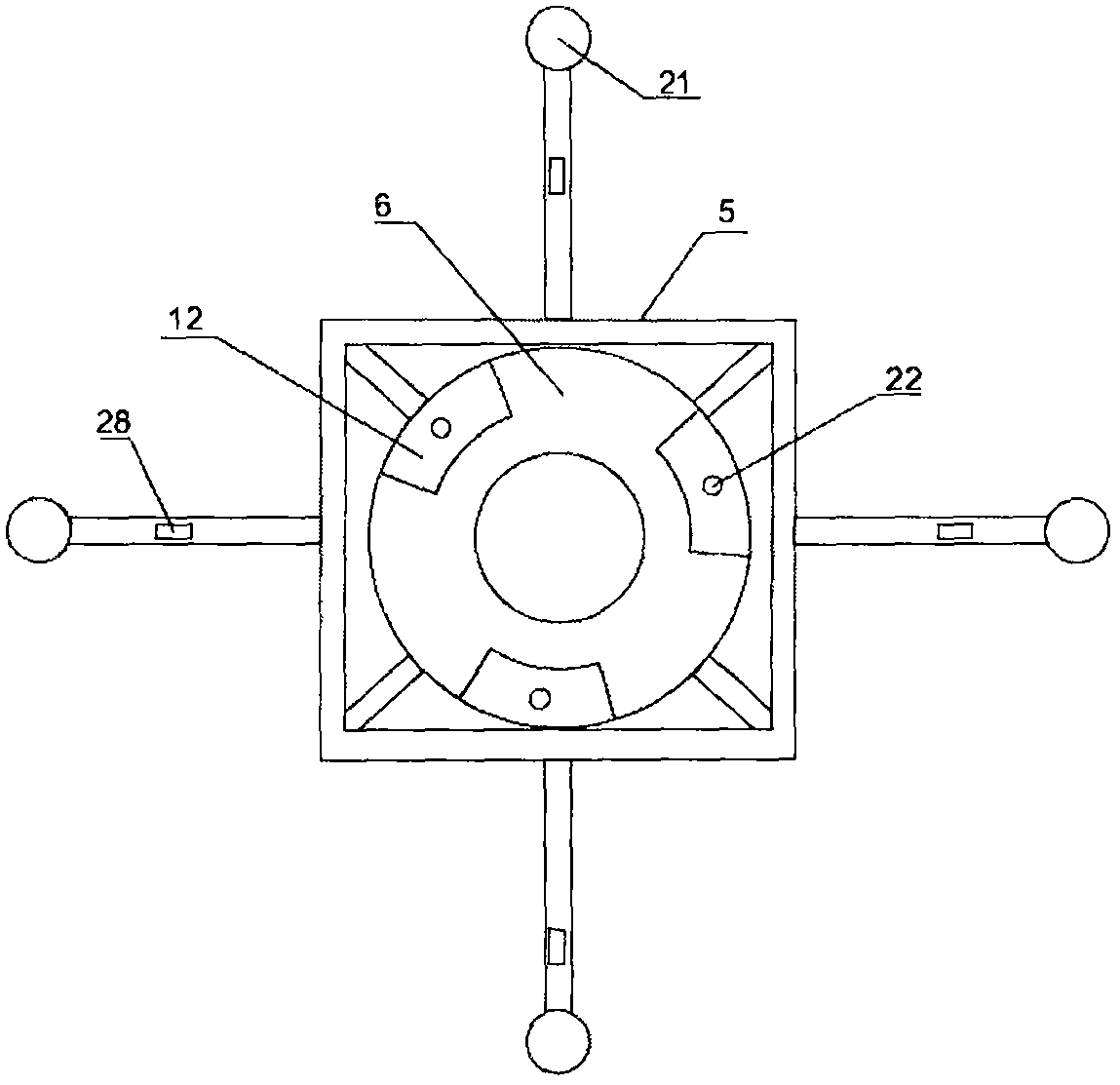
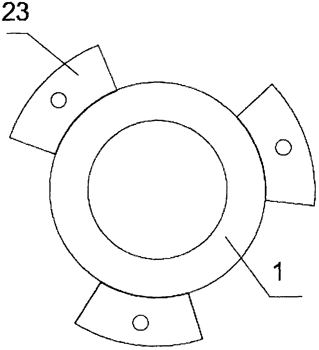
[0020] Such as figure 1 As shown, a kind of submarine seismograph delivery device of the present invention comprises a sinking coupling frame, an instrument tank is arranged on the sinking coupling frame, and the sinking coupling frame includes a square frame platform 5 and a deflector 21, and the center of the frame platform 5 is provided with a circle shaped mounting base 6, the instrument tank is detachably connected to the mounting base 6, the instrument tank includes an outer protective tank body 1 and an inner protective tank body sleeved in the outer protective tank body 1, the inner protective tank body and the outer protective tank body 1 A vacuumed isolation space is formed between them, which can reduce the impact of ocean currents on the submarine seismograph 4, and minimize the inward conduction of seawater temperature, thereby reducing the impact of seaw...


PUM


Abstract

The invention discloses an ocean bottom seismograph placement device, which comprises a submerged coupling frame, wherein an instrument tank is arranged on the submerged coupling frame; the submergedcoupling frame comprises a square framework platform and a flow guide cover; a circular mounting base is arranged at the center of the framework platform; the instrument tank is detachably connected to the mounting base; the instrument tank comprises an external protective tank body and an internal protective tank body arranged in the external protective tank body in a sleeved manner; the internalprotective tank body comprises an upper spherical tank and a lower mounting tank which are integrally connected; a storage battery is arranged in the upper spherical tank; an ocean bottom seismographis arranged in the lower mounting tank; a balance suspension assembly is arranged at the top of the external protective tank body. The ocean bottom seismograph placement device disclosed by the invention has the beneficial effects that the instrument tank and the submerged coupling frame are mounted conveniently and firmly; during placement, equipment can be kept falling down onto the ocean bottom horizontally; an isolation space is reserved between the internal protective tank body and the external protective tank body, so that impact influence caused by ocean current on the ocean bottom seismograph is reduced, inward conduction of sea water temperature is reduced as much as possible, and the monitoring precision of the ocean bottom seismograph is improved.

Description

technical field [0001] The invention relates to a launching device for a seabed seismograph. Background technique [0002] The ocean bottom seismometer (OBS) and its subsea seismic observation are high-tech developed in recent years. They are widely used in oil and gas exploration, scientific research, disaster prevention and mitigation, etc. A new growth point in development. [0003] The submarine seismograph is a seismic observation system that places the geophone directly on the seabed. In marine geophysical investigation and research, it can be used not only for the detection of marine artificial seismic profiles, but also for the observation of natural earthquakes. The detection and observation results can be used to study the velocity structure of the oceanic crust and mantle and the dynamic characteristics of the evolution of plate subduction zones, trenches, and troughs, and can also be used to study seismic tomography of natural earthquakes, seismic activity and e...

Claims


Application Information

Patent Timeline
IPC IPC(8): G01V1/38
CPCG01V1/3852
Inventor 周宝峰任叶飞温瑞智
Owner INST OF ENG MECHANICS CHINA EARTHQUAKE ADMINISTRATION
Learn More