Method and system for monitoring abnormities in the technique process
A process and abnormal technology, applied in the abnormal field in the monitoring process, can solve problems such as affecting the monitoring accuracy, and achieve the effect of reducing unnecessary alarms, improving work efficiency, and reducing negative feelings.
- Summary
- Abstract
- Description
- Claims
- Application Information
AI Technical Summary
Problems solved by technology
Method used
Image

Examples
Embodiment 1
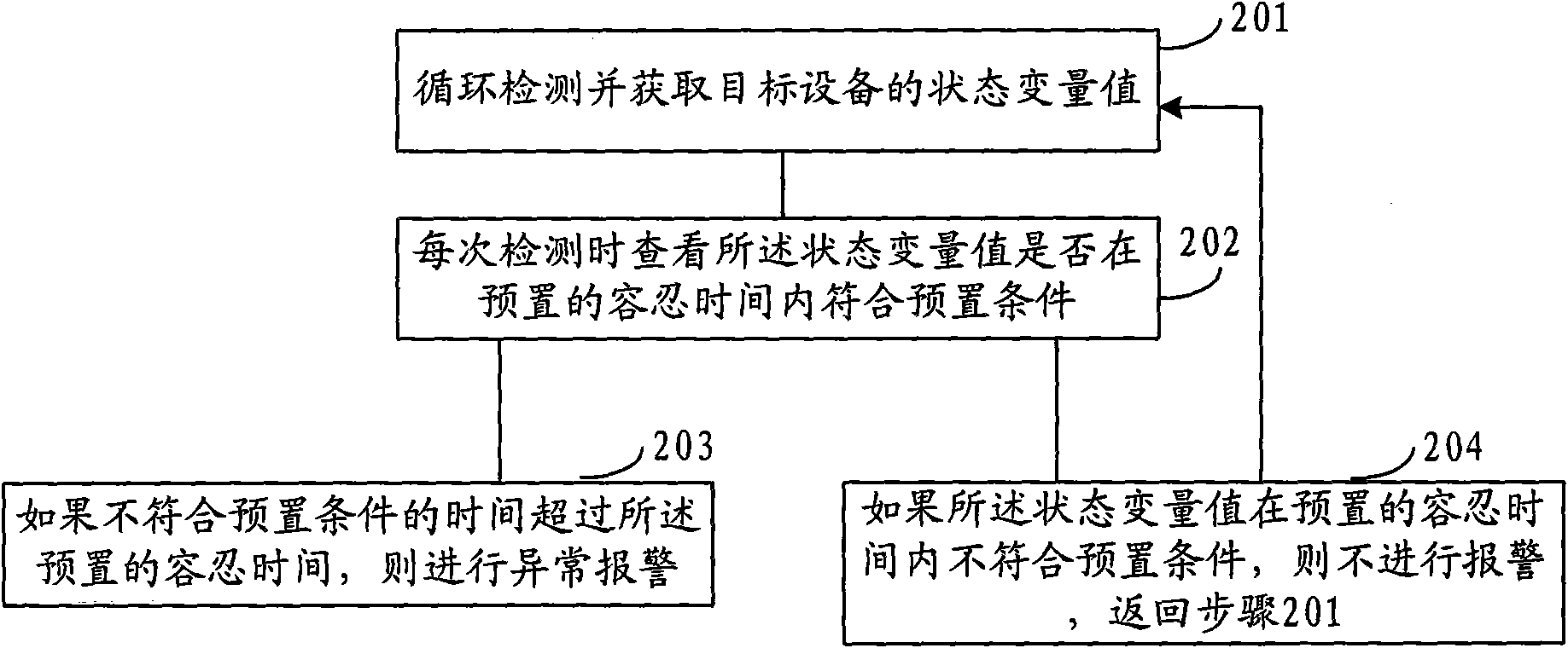
[0051] refer to figure 2 , is a flowchart of a method for monitoring abnormalities in a process described in Embodiment 1 of the present invention.
[0052] Step 201, cyclically detect and obtain the state variable value of the target device;
[0053] Cyclic detection refers to repeatedly detecting the state variables of the target device according to a certain time interval.
[0054] The target device refers to a device that needs to be monitored for abnormality, and whether the device is normal is monitored by detecting the target device and obtaining a corresponding state variable value. Different target devices have different state variables that need to be monitored. For example, device A needs to monitor temperature variables, and device B needs to monitor pH variables; moreover, the same target device also has multiple state variables that need to be monitored. For example, device C needs to monitor simultaneously Temperature and pH variables.
[0055] It should be no...
Embodiment 2
[0072] This embodiment is described through a specific implementation manner.
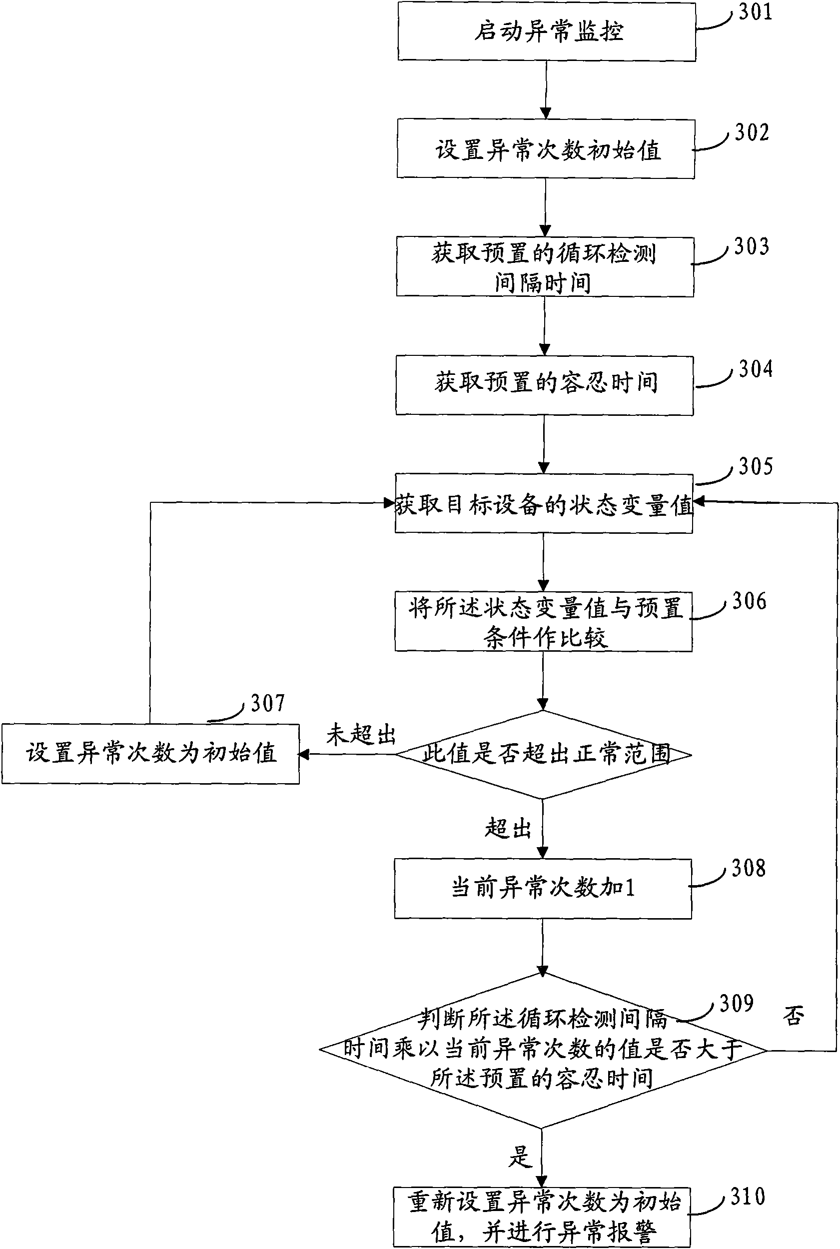
[0073] refer to image 3 , is a flowchart of a method for monitoring abnormalities in a process described in Embodiment 2 of the present invention. This embodiment is also described by taking the monitoring of a state variable as an example.
[0074] Step 301, start abnormality monitoring;
[0075] Step 302, setting the initial value of abnormal times;
[0076] That is, the initialization operation is performed, for example, the initial value of the number of exceptions can be set to 0;
[0077] Step 303, obtaining a preset cycle detection interval time;
[0078] Step 304, acquiring a preset tolerance time;
[0079] Wherein steps 303 and 304 do not limit the sequential acquisition sequence;
[0080] Step 305, obtaining the state variable value of the target device;
[0081] Step 306, comparing the value of the state variable with a preset condition;
[0082] That is, it is judged whether th...
Embodiment 3
[0100] Based on the above method embodiments, the present invention also provides corresponding system embodiments.
[0101] refer to Figure 4 , is a structural diagram of a system for monitoring abnormalities in a process described in Embodiment 3 of the present invention. The system mainly includes:
[0102] A device state acquisition unit 41, configured to loop detection and obtain the state variable value of the target device;
[0103] An abnormality monitoring unit 42, configured to check whether the value of the state variable meets a preset condition within a preset tolerance time during each detection;
[0104] The alarm unit 43 is configured to issue an abnormal alarm when the state variable value does not meet the preset condition for a period exceeding the preset tolerance time.
[0105] The above abnormality monitoring system does not alarm for tolerable abnormalities, thereby improving the accuracy of abnormality monitoring. Moreover, it helps to improve the ...
PUM
 Abstract
Description
Claims
Application Information
 - R&D
- Intellectual Property
- Life Sciences
- Materials
- Tech Scout
- Unparalleled Data Quality
- Higher Quality Content
- 60% Fewer Hallucinations
Browse by: Latest US Patents, China's latest patents, Technical Efficacy Thesaurus, Application Domain, Technology Topic, Popular Technical Reports.
© 2025 PatSnap. All rights reserved.Legal|Privacy policy|Modern Slavery Act Transparency Statement|Sitemap|About US| Contact US: help@patsnap.com