
Camera system and method thereof

A camera system and camera technology, applied in the field of camera systems, can solve the problems of high cost, high system circuit complexity, and high system software complexity, and achieve the effects of simplifying circuits and driving software, improving system stability, and reducing costs.

Inactive Publication Date: 2010-03-17
深圳市经纬科技有限公司
View PDF0 Cites 26 Cited by
  • Summary
  • Abstract
  • Description
  • Claims
  • Application Information

AI Technical Summary

Problems solved by technology

[0009] The technical problem to be solved by the present invention is that the cost of the above-mentioned entire product in the prior art is high, the complexity of the system circuit is high, the software complexity of the system is high, and defects such as the main control processor chip are not fully utilized, providing Camera system and method thereof

Method used


Image

  • Camera system and method thereof
  • Camera system and method thereof
  • Camera system and method thereof

Examples


Embodiment Construction

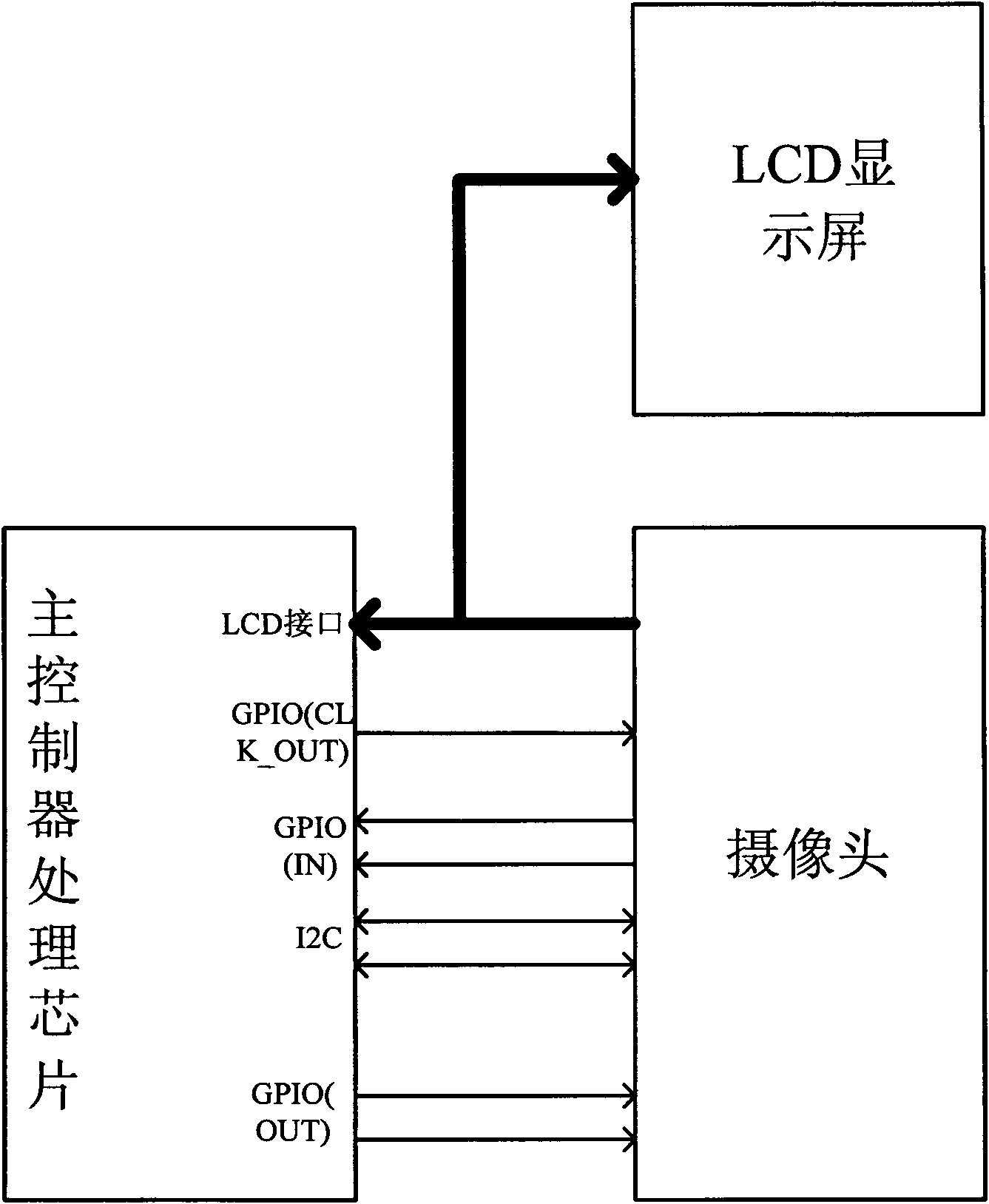
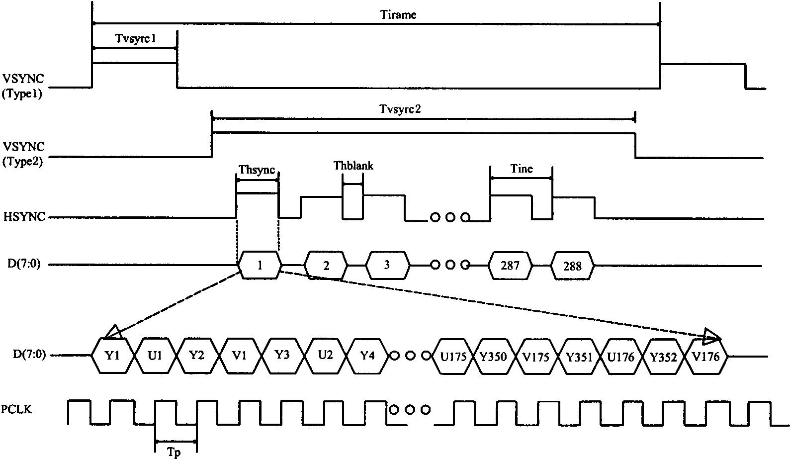
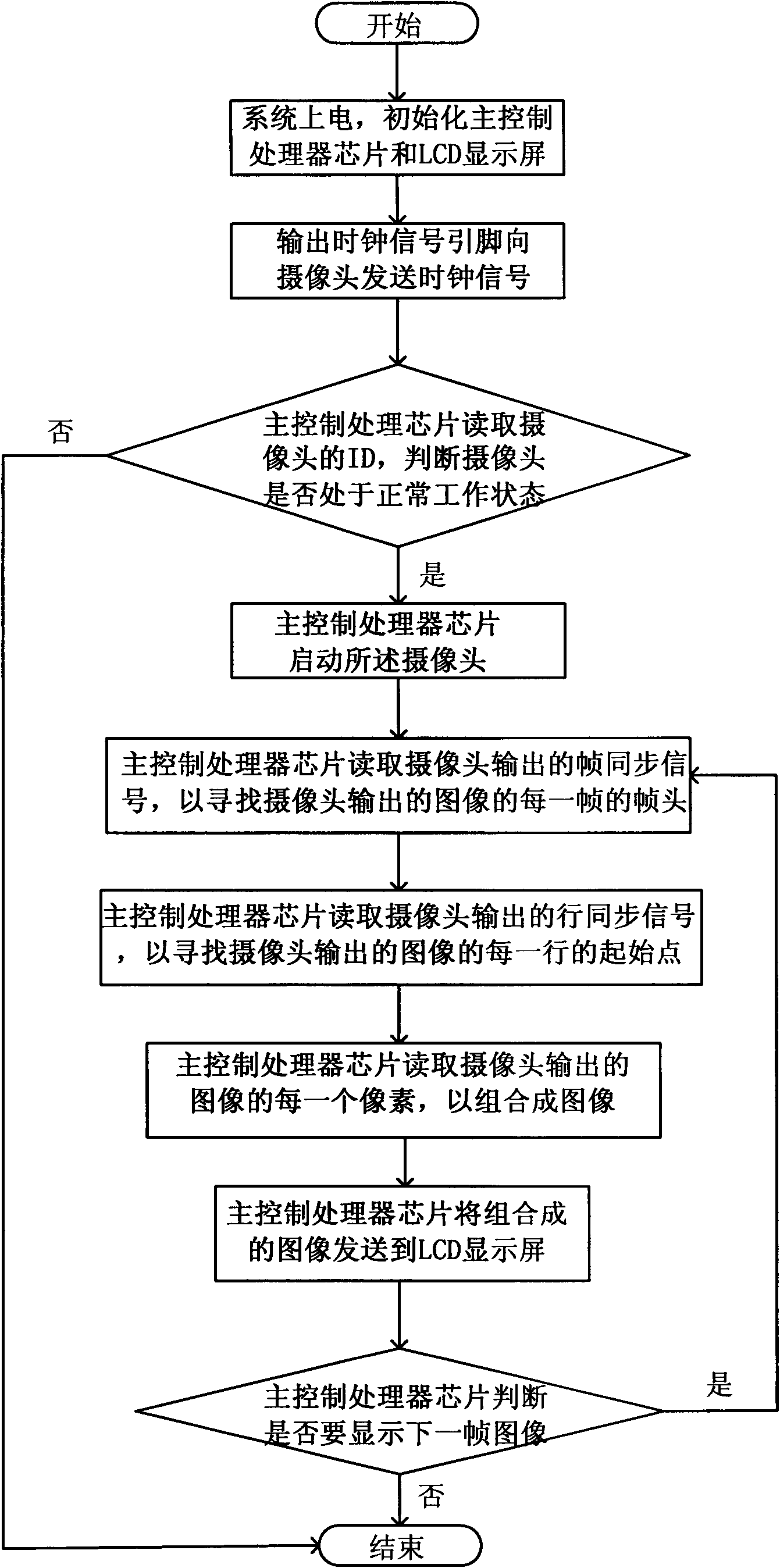
[0036] Such as figure 1 As shown, the camera system of the present invention includes a main control processor chip, an LCD display and a camera, and the LCD display and the camera are directly connected to the LCD display of the main control processor chip through a shared 8-bit data bus. Interface, thereby canceling the related controller and co-processor added for the camera in the prior art. The camera is also connected to the output clock signal pin, synchronization signal detection pin and general input / output pin of the main control processor chip. And I2C bus interface. In addition, the chip selection CS for the camera and the LCD display can be shared or used separately. When the data line connecting the main control processor chip and the LCD display is independent, the buffer can be removed. The camera is mainly composed of a lens, an image sensing unit, and related circuits. The video signal is collected by the camera, and encoded into a specified format after pas...


PUM


Abstract

The invention relates to a camera system and a control method thereof. The system comprises a main control processor chip, an LCD display screen and a camera, wherein the LCD display screen and the camera are directly connected with an interface of the LCD display screen of the main control processor chip by a shared data line, and the camera is respectively connected with a clock signal output pin, a synchronous signal detection pin, a general-purpose input / output pin and an I2C bus interface. The camera system and the control method thereof are implemented by adding the camera and video record functions of a product with the camera system, such as a cellphone, a digital camera, and the like with the minimum cost by omitting a special control processor used for the camera. In addition, the invention adopts the technology as follows: multiplexing pins with the general-purpose input / output and clock output functions are adopted to simulate a clock signal and control the operation of thecamera so that the camera and the main control processor chip can synchronously work and image information output by the camera can be read by a data bus of the main control processor chip.

Description

Technical field [0001] The present invention relates to a camera device, and more specifically, to a camera system and a method thereof. Background technique [0002] The existing image sensor mainly has two kinds of devices, one is CCD (Charge Couple Device), and the other is CMOS (Complementary Metal Oxide Semiconductor). The camera with CMOS sensor technology has a built-in photosensitive matrix. The matrix size is related to the resolution. For example, VGA has 640x480 pixels, and CIF has 352x288 pixels. Each pixel is composed of three photosensitive units of red R, green G, and blue B, and each photosensitive unit has an ADC analog-to-digital conversion unit connected to it. The photosensitive unit is made on the wafer with integrated circuit semiconductor manufacturing technology. The lens system of the camera module projects the external image onto the photosensitive matrix. The photosensitive unit of the corresponding color generates voltages (currents) of different in...

Claims


Application Information

Patent Timeline
Patent Type & Authority Applications(China)
IPC IPC(8): H04N5/225H04N5/232
Inventor 许毅勇
Owner 深圳市经纬科技有限公司
Learn More