Insulating material for electrical machines

A technology of insulating materials and electrical equipment, applied in electrical components, transformer/inductor parts, circuits, etc., can solve the problems of damage to winding life, reduce power, etc., and achieve the effect of improving life, small mechanical load, and simple handling

Inactive Publication Date: 2010-03-17
SIEMENS AG
View PDF1 Cites 2 Cited by
  • Summary
  • Abstract
  • Description
  • Claims
  • Application Information

AI Technical Summary

Problems solved by technology

[0005] In the case of loosened or cracked insulation, glow discharges can occur between individual turns of the winding, which reduces power and impairs the life of the winding

Method used


Image

  • Insulating material for electrical machines
  • Insulating material for electrical machines
  • Insulating material for electrical machines

Examples


Embodiment Construction

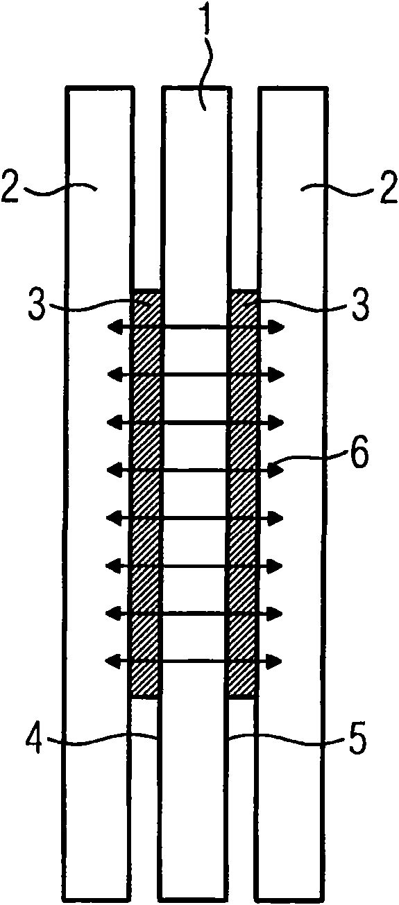
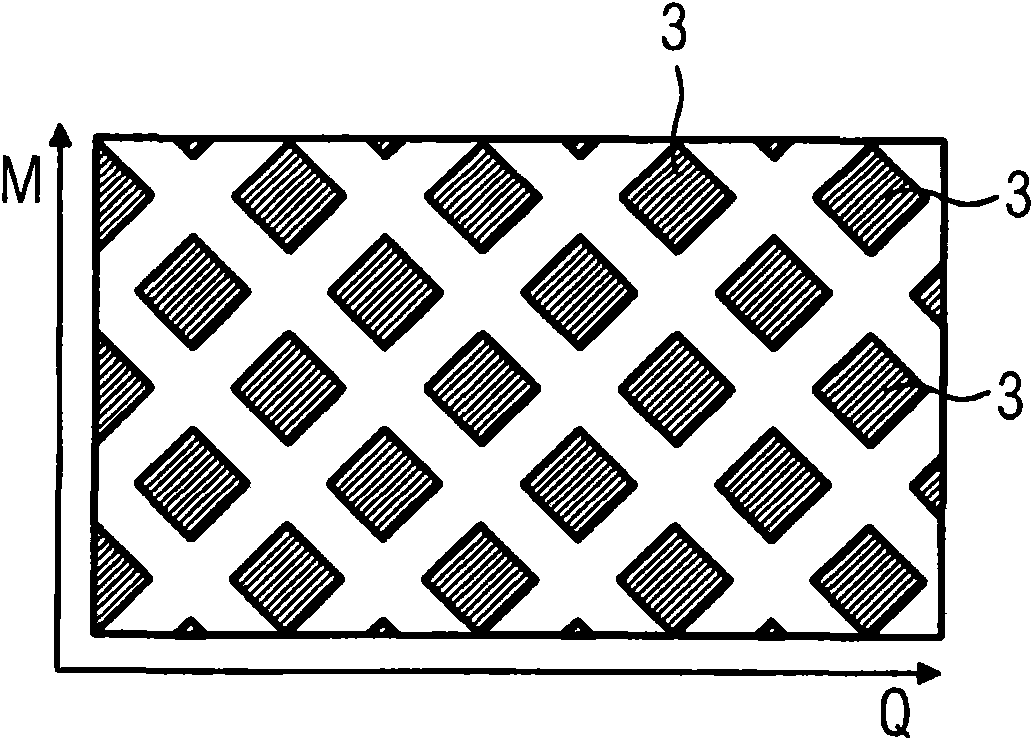
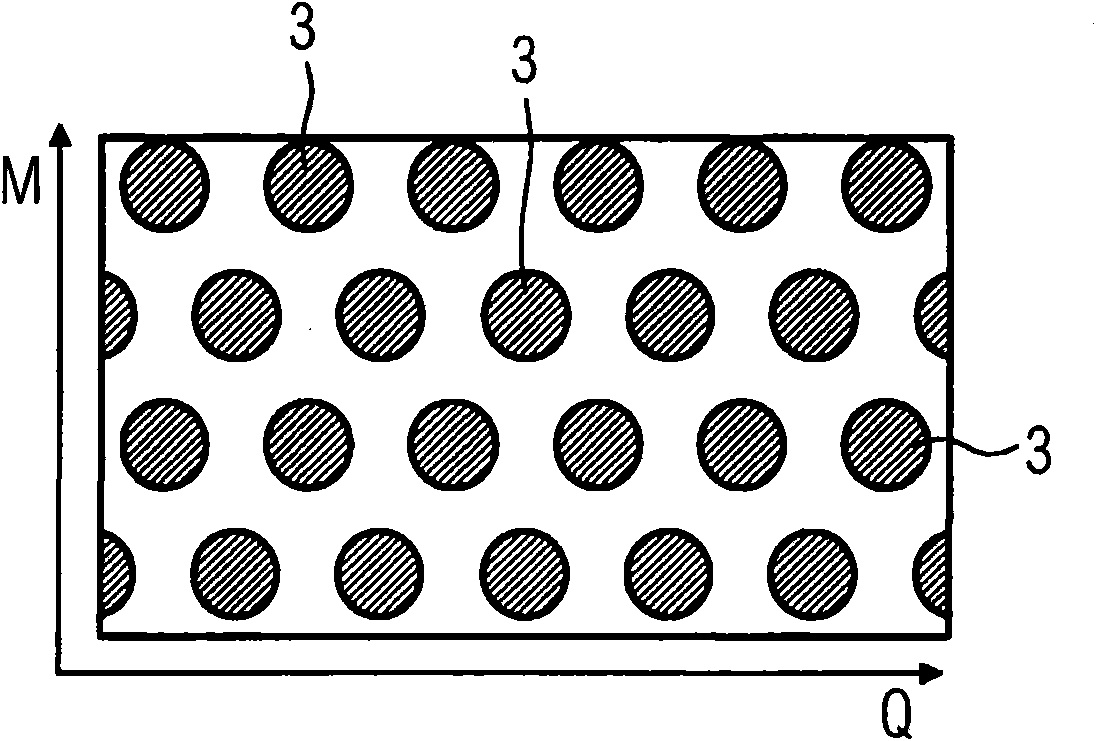
[0023] exist figure 1 A schematic diagram of the principle of force bonding connection of the present invention is shown in . An adhesive layer 3 is arranged on the carrier material 1 on the front side 4 and the rear side 5 . The adhesive layer 3 contacts the turns 2 in an insulated state by baking or bonding. Because the adhesive layers 3 lie directly or congruently opposite one another on the front side 4 and the rear side 5 of the carrier material 1 , a direct non-positive connection is formed between the respectively opposing adhesive layers 3 . As a result, no shear forces develop on the carrier material 1 since the forces are transmitted directly from one side to the other. Due to this direct force-bonding connection, the following advantages are obtained in particular:

[0024] - Baking or bonding of insulating material to turns 2 of electrical conductors of electrical equipment (eg transformers, transmitters, generators) results in high stability

[0025] - resulti...


PUM


Abstract

Insulating material for electrical machines for insulating coiled windings, having a carrier material and adhesive coatings on the front and back of the carrier material, the adhesive coatings being mounted and aligned on the front and back of the carrier material in such a way that in the carrier material in the insulation state a direct frictional connection is developed between the adhesive coatings on the front and back.

Description

technical field [0001] The invention relates to an insulating material for electrical equipment, for insulating wound turns, which has a carrier material and adhesive layers on the front and back of the carrier material. [0002] Furthermore, the invention relates to the use of an insulating material for insulating wound wire turns in electrical installations. Background technique [0003] It has long been known to use insulating materials for the insulation of windings of electrical devices (eg transformers, transmitters), which are pressed on both sides with epoxy resin. Typically this insulation has a diamond-shaped epoxy coating. In technical terms, this insulating material is called "Diamond Pattern Epoyy Coated Paper" (DPP). [0004] An insulating material is known from European patent application EP 0 287 814 B1, which comprises an insulating layer made of an organic polymer. This European patent application discloses an insulating material with improved glow inten...

Claims


Application Information

Patent Timeline
Patent Type & Authority Applications(China)
IPC IPC(8): C09J7/02C09J7/21C09J7/35
CPCC09J7/043H01F30/12C09J2463/00H01F27/2876C09J2400/263C09J2467/006H01F27/323C09J2201/28C09J7/0203C09J2203/302C09J2400/283C09J7/35C09J7/21Y10T428/24934Y10T428/24802C09J2301/204
Inventor G·希普茨基G·鲁斯
Owner SIEMENS AG
Why Eureka
Try Eureka