Clutch assembly

A clutch and assembly technology, applied in the direction of clutches, mechanical drive clutches, mechanical equipment, etc., can solve the problem of high manufacturing cost of synchronous rings, and achieve the effects of low cost, reduced installation space, and low cost

Inactive Publication Date: 2010-03-17
HOERBIGER ANTRIEBSTECHN HLDG
View PDF2 Cites 20 Cited by
  • Summary
  • Abstract
  • Description
  • Claims
  • Application Information

AI Technical Summary

Problems solved by technology

[0011] However, in this type of synchronized clutch assembly, the manufacturing cost of the synchronizer ring is also relatively high

Method used


Image

  • Clutch assembly
  • Clutch assembly
  • Clutch assembly

Examples


Embodiment Construction

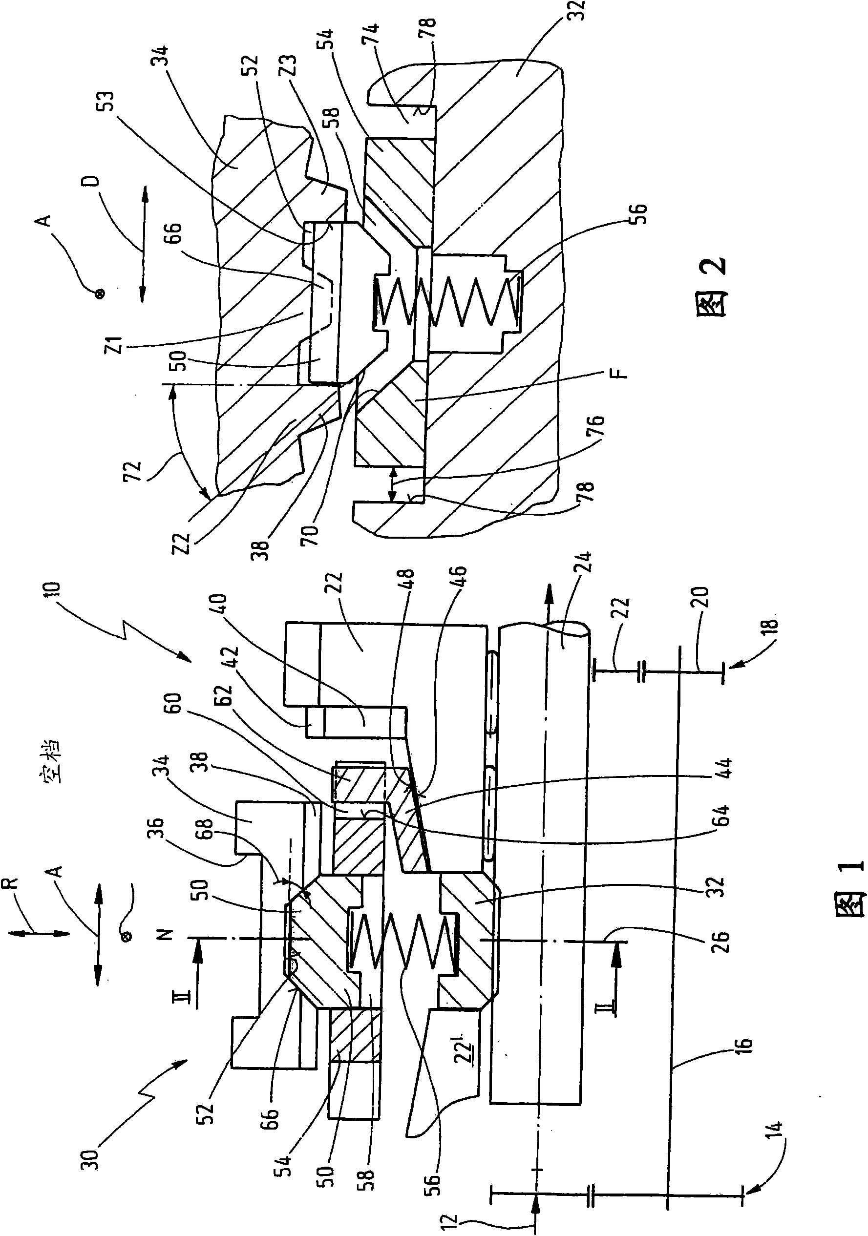
[0092] exist figure 1 and 2 A transmission for a motor vehicle is indicated generally at 10 in .

[0093] The transmission 10 has an input shaft 12 , which is connected via a constant gear set 14 to an intermediate shaft 16 , which is parallel to the input shaft.

[0094] The output shaft 24 is arranged coaxially with the input shaft 12 . A plurality of ratchet sets 18 are disposed on an intermediate or output shaft 24 . exist figure 1 For reasons of clarity, only one ratchet set 18 is shown, which has a fixed gear 20 which is connected to the intermediate shaft 16 . The ratchet set 18 also has an idler gear 22 , which is rotatably mounted on an output shaft 24 .

[0095] exist figure 1 The other idler gear 22' is only schematically shown in FIG.

[0096] Of course, the shown transmission device, which is designed for longitudinal installation in a vehicle, represents only one example. The invention can likewise be applied to transmissions with other layouts (eg for fr...


PUM


Abstract

A clutch assembly for connecting a shaft to a rotary member mounted on said shaft in a rotationally fixed manner comprises: a sliding sleeve which is rotationally fixed to the shaft, is axially slidably mounted on said shaft and is provided with a first gearing, A clutch body which is rotationally fixed to the rotary member and provided with a second gearing which can mesh with the first gearing to connect the shaft and the rotary member in a rotationally fixed manner. And, a locking synchronisation unit having a synchroniser ring with a friction surface the ring permitting the speeds of the shaft and the rotary member to be synchronised before the meshing of the first and second gearings. The locking synchronisation unit further comprises a locking member which is coupled to the sliding sleeve by a detent groove and to the synchroniser ring in the rotational direction (D) by a pair of locking surfaces. The pair of locking surfaces are situated between the locking member and a synchroniser member, the latter being coupled to the locking member in the axial direction (A) and to the synchroniser ring in the rotational direction (D).

Description

technical field [0001] The invention relates to a clutch assembly for torque-proof connection of a shaft with a rotating member arranged thereon, such as an idler gear, wherein the clutch assembly has a shift sleeve which is torque-proof connected to the shaft and opposite The shaft is displaceably arranged in the axial direction and is equipped with first gear teeth; the clutch body is connected to the rotating member in a rotationally fixed manner and is equipped with second gear teeth, in order to connect the shaft to the rotating member in a rotationally fixed manner. Two gear teeth are meshable with the first gear teeth; and a lock-synchronization device having a synchronizing ring with a friction surface, by means of which, before the first and second gear teeth mesh, the rotational speed of the shaft and the rotating member Synchronization is possible, wherein the locking-synchronizing device also has a locking element, which is connected to the shifting sleeve via lock...

Claims


Application Information

Patent Timeline
Patent Type & Authority Applications(China)
IPC IPC(8): F16D23/06
CPCF16D23/06F16D2023/0618Y10T74/19284F16D23/02F16D23/04
Inventor 埃罗尔·勒代斯基约亨·克伦克勒
Owner HOERBIGER ANTRIEBSTECHN HLDG
Why Eureka
Try Eureka