
Pressure release type backflow preventer

A technology of backflow preventer and pressure relief, which is applied in the direction of valve details, control valves, function valve types, etc., can solve the problems of ineffective prevention of pressure water backflow pollution, unsuccinct valve core structure, and difficult diaphragm processing, etc., to achieve The design calculation is convenient, the processing difficulty is overcome, and the processing is simple.

Inactive Publication Date: 2010-03-24
NINGBO HUACHENG VALVE
View PDF0 Cites 14 Cited by
  • Summary
  • Abstract
  • Description
  • Claims
  • Application Information

AI Technical Summary

Problems solved by technology

[0002] In all kinds of water supply pipelines, the various check valves currently used cannot effectively prevent backflow pollution from backflow of pressure water from the branch pipe to the main pipe, especially in the water supply network of domestic drinking water. serious harm to the health of
Become a hidden danger of unsafe liquid supply in the production process
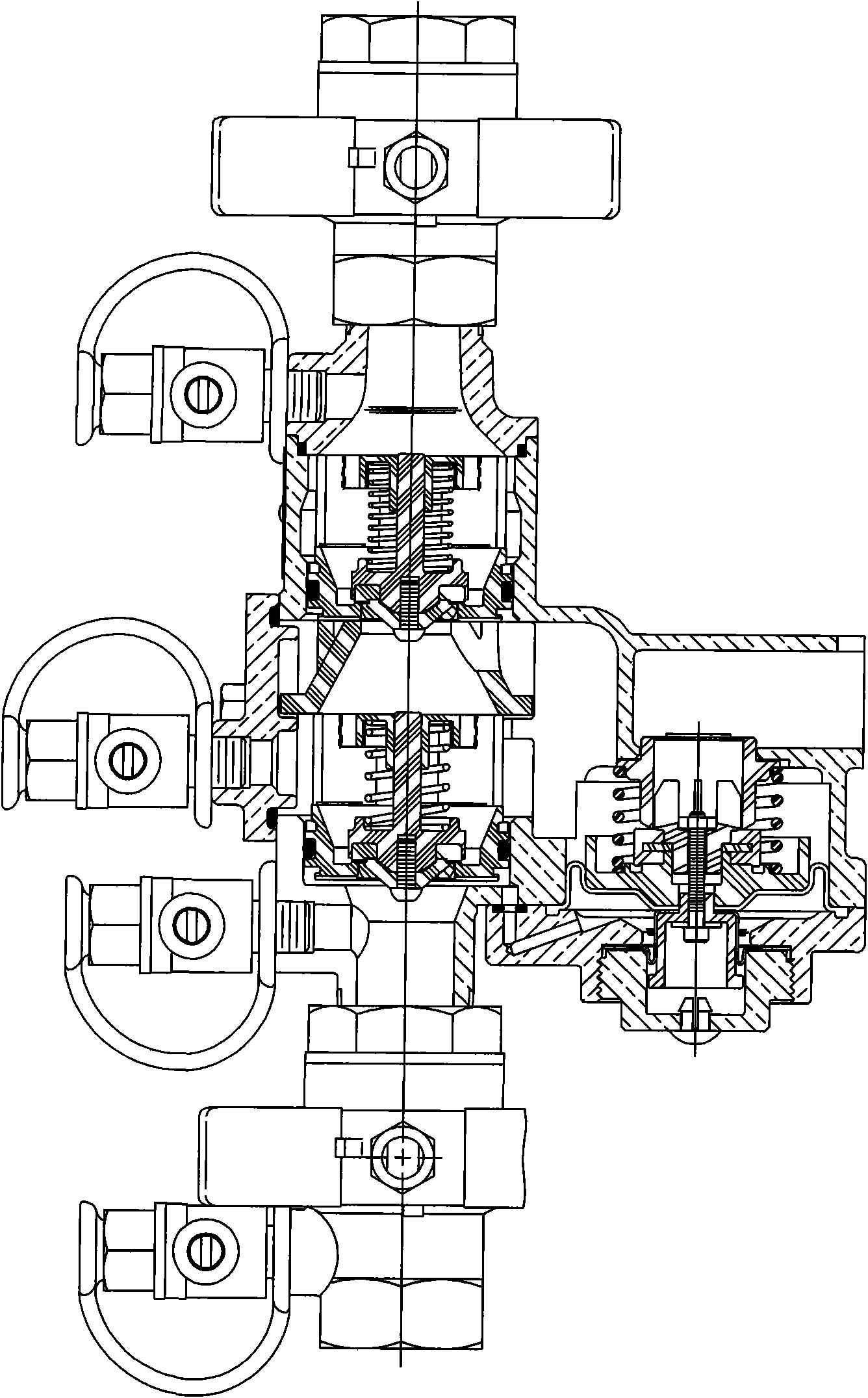
[0003] For this reason, some scientific and technical personnel have developed a pressure relief type backflow preventer, which consists of a water inlet ball valve, a water outlet ball valve, a primary check valve, a secondary check valve, and a water relief pressure reducing valve bypassing it. The pressure reducing valve is installed between the first-stage check valve and the second-stage check valve. For the specific structure, see figure 1 The spool that can move left and right is arranged in the inner cavity of the drain pressure reducing valve. The spool is connected by a small piston and a large piston with bolts, and both the small piston and the large piston are equipped with a diaphragm pad to divide the inner cavity into left and right. The disadvantage of the chamber is that the valve core structure is not simple enough, and the diaphragm processing is difficult, the technology is difficult to master, and there is a reaction force, so the design needs to be further improved

Method used


Image

  • Pressure release type backflow preventer
  • Pressure release type backflow preventer

Examples


Embodiment Construction

[0012] The present invention will be further described in detail below with reference to the embodiments of the accompanying drawings.

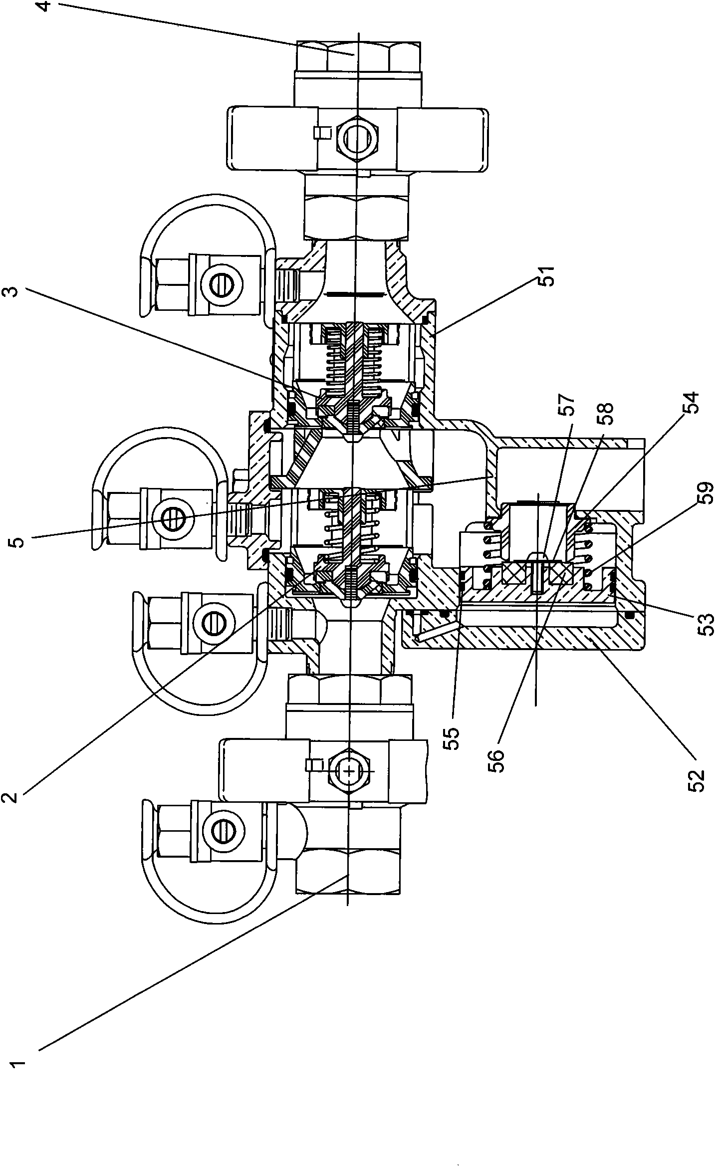
[0013] like figure 1 As shown, a pressure relief type backflow preventer, which includes a water inlet ball valve 1, a primary check valve 2, a secondary check valve 3, a water outlet ball valve 4, and a bypassed water relief valve 5 are installed in sequence. Between the primary check valve 2 and the secondary check valve 3, the drain relief valve 5 is divided into a valve cover 52 of the drain relief valve and a valve body 51 of the drain relief valve, a piston body that can move left and right 53 is arranged in the inner cavity of the water relief valve to divide it into a left chamber and a right chamber. The piston body 53 can be made of anti-corrosion plastic. The water inlet is connected, and the right chamber communicates the water inlet and the water outlet of the water relief valve through the annular seat 54. There are two annular...


PUM


Abstract

The invention relates to a pressure release type backflow preventer which comprises a water inlet ball valve, a first-stage check valve, a second-stage check valve and a water outlet ball valve, wherein a bypass draining pressure reducing valve is installed between the first-stage check valve and the second-stage check valve and comprises a valve cover and a valve body. The backflow preventer is characterized in that a piston body which can move left and right is distributed inside an inner cavity of the draining pressure reducing valve and divides the inner cavity into a left cavity and a right cavity, wherein the left cavity is communicated with a master water inlet by a channel arranged on the valve cover of the draining pressure reducing valve, and the right cavity leads a water inletto be communicated with a water outlet of the draining pressure reducing valve by a ring-shaped seat; the circumferential surface of the piston body is distributed with a ring-shaped sealing ring which is used for realizing sliding seal with the wall surface of the inner cavity, and the right side of the piston body is provided with a gasket which is matched and sealed with the ring-shaped seat; and a spring is supported between the piston body and the ring-shaped seat. Therefore, the pressure release type backflow preventer has simple and reasonable structure, and is easy to produce and assemble.

Description

technical field [0001] The invention relates to an anti-backflow valve device. Background technique [0002] In all kinds of water supply pipelines, the various check valves currently used cannot effectively prevent the pressure water from flowing back from the branch pipe to the main pipe and causing backflow pollution, especially in the water supply network of drinking water. serious health hazards. In the production process, it becomes a hidden danger of unsafe liquid supply. [0003] For this reason, some scientific and technical personnel have developed a pressure relief type backflow preventer, which consists of a water inlet ball valve, a water outlet ball valve, a primary check valve, a secondary check valve and a water relief valve bypassed by it. The pressure reducing valve is installed between the primary check valve and the secondary check valve. For the specific structure, see figure 1 , The spool that can move left and right is arranged in the inner cavity o...

Claims


Application Information

Patent Timeline
Patent Type & Authority Applications(China)
IPC IPC(8): F16K15/18F16K15/00F16K31/12
Inventor 王朝阳连超燕祝云霞
Owner NINGBO HUACHENG VALVE
Learn More