Equalizing plate structure

A technology of vapor chamber and metal plate, applied in lighting and heating equipment, indirect heat exchanger, cooling/ventilation/heating transformation, etc., can solve problems such as welding defects, and achieve the effect of increasing efficiency

Inactive Publication Date: 2010-03-24
铭懋工业股份有限公司
View PDF0 Cites 9 Cited by
  • Summary
  • Abstract
  • Description
  • Claims
  • Application Information

AI Technical Summary

Problems solved by technology

[0003] In view of the deficiencies in the prior art, the purpose of the present invention is to p

Method used


Image

  • Equalizing plate structure
  • Equalizing plate structure
  • Equalizing plate structure

Examples


Embodiment Construction

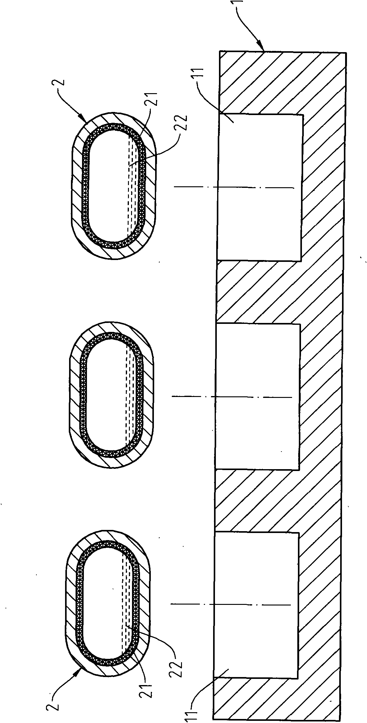
[0018] see Figure 1 to Figure 4 As shown, it can be clearly seen from the figure that the present invention is provided with a metal plate 1 and a heat pipe 2, wherein:

[0019] A plurality of accommodating spaces 11 are recessed on the surface of the metal plate 1 .

[0020] The inner wall of the heat pipe 2 is sintered with a capillary structure 21 , and an appropriate amount of working fluid 22 is stored in the heat pipe 2 .

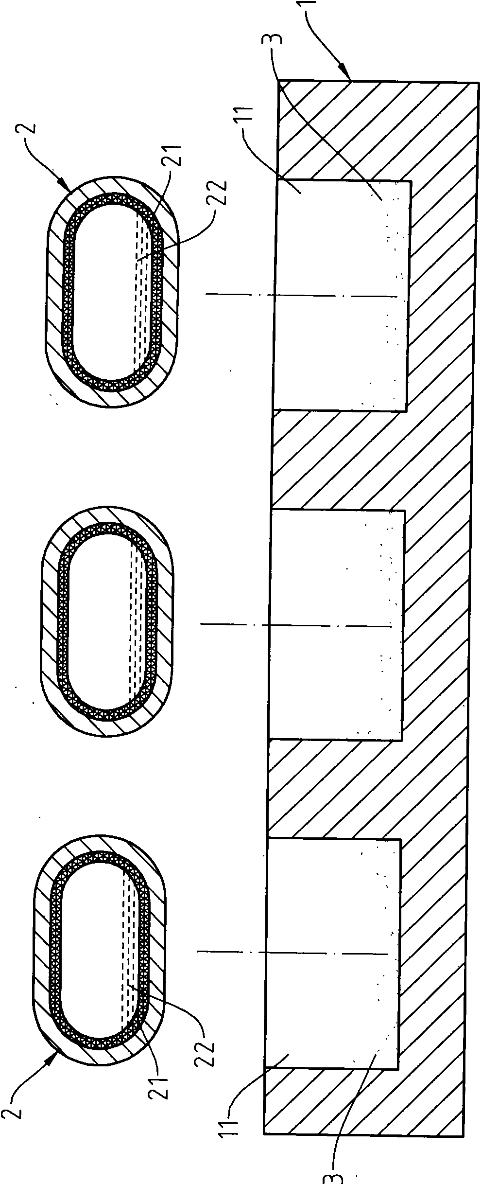
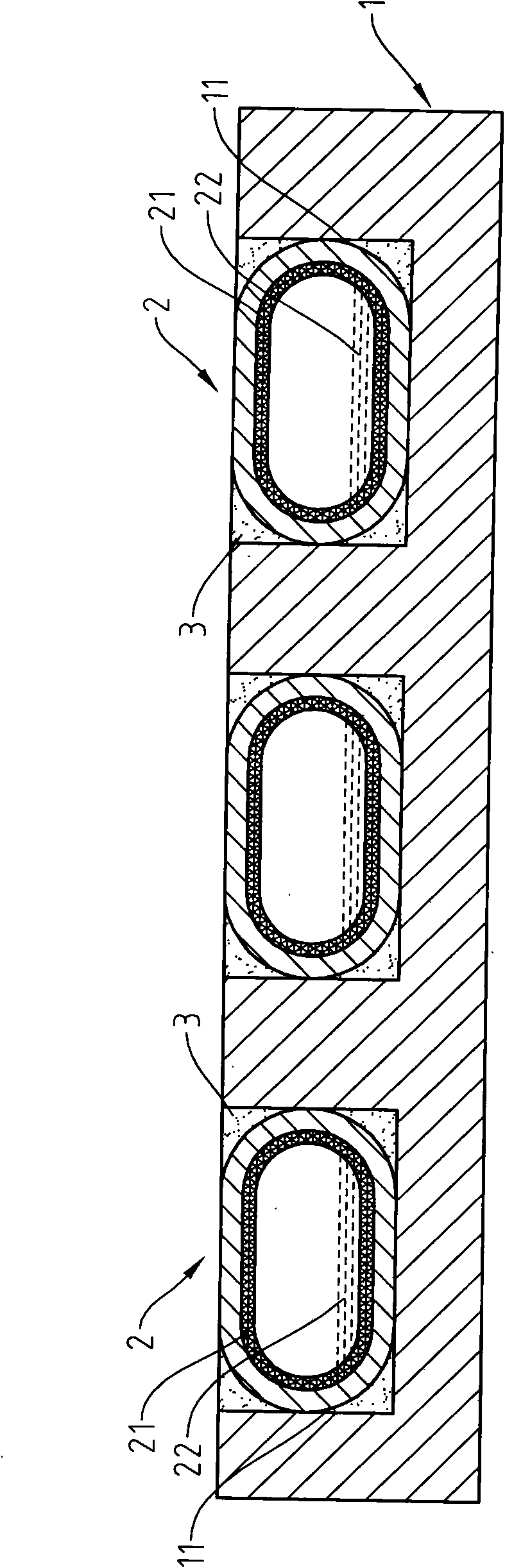
[0021] When the vapor chamber of the present invention is manufactured, an appropriate amount of solder 3 is first coated in the accommodation space 11, and the heat pipes 2 are prefabricated into a geometric shape close to the accommodation space 11, and then each heat pipe 2 is inserted into the metal In the accommodating space 11 of the plate 1, at this time, the solder 3 will fill in the gap formed by the heat pipe 2 and the accommodating space 11, and then the metal plate 1 is sent to the reflow furnace for heating, so that the heat pipe 2 and ...


PUM


Abstract

The invention relates to an equalizing plate structure, in particular to an equalizing plate structure capable of rapidly conducting heat energy produced by a heating element. The equalizing plate ismade by the steps that proper amount of soldering flux is coated in the containing space concavely arranged on the surface of a metal plate (copper plate or aluminium plate), a heat pipe is made intogeometry shape close to the containing space in advance, each heat pipe is placed into the concavely arranged containing space coated with soldering flux, the metal plate is heated in a reflow oven tobe heated, so that the heat pipe and the metal plate can be adhered tightly by soldering flux, the upper surface and the lower surface of the metal plate are milled or ground to be flat, the plane ofthe heat pipe respectively exposes out of the surface of the metal plate, and the plane of the heat pipe is parallel with the surface of the metal plate, thus, the heat absorption area of the equalizing plate is directly contacted with heat source, efficiency of heat conduction and heat diffusivity is improved, and further the heat energy continuously produced by the heating element can be conducted to distal end by the equalizing plate continuously, so as to maintain that the heating element normally operates at allowable temperature.

Description

technical field [0001] The invention relates to a cooling device for electronic components. Background technique [0002] With the rapid development of the technology industry, the electronic components are getting faster and faster in calculation execution, and the heat generated during their operation is also getting higher and higher. In order to effectively dissipate this heat, to maintain the electronic components in the allowable To be able to operate under high temperature, heat dissipation devices are usually installed on the electronic components, and the common heat dissipation device is to install heat dissipation fins on the metal plate, so that the metal plate contacts the electronic components and absorbs the heat energy emitted by them, and then conducts the heat energy to the heat sink. Fins dissipate heat. However, as the calculation speed of electronic components increases, the heat generated by them becomes higher and higher. Generally, heat sinks that use...

Claims


Application Information

Patent Timeline
IPC IPC(8): F28D15/02H05K7/20
Inventor 黄国文
Owner 铭懋工业股份有限公司
Why Eureka
Try Eureka