Diagnostic camera and attachment for the implementation thereof

A camera and top cover technology, applied in the camera body, diagnosis, camera and other directions, can solve the problem of non-blurred diagnosis camera image, difficult to capture, etc., to achieve the effect of strong manufacturing, low distortion, and reliable connection

Inactive Publication Date: 2010-03-24
DURR DENTAL GMBH & CO KG
View PDF0 Cites 11 Cited by
  • Summary
  • Abstract
  • Description
  • Claims
  • Application Information

AI Technical Summary

Problems solved by technology

Restricted by working conditions (bending posture, it is difficult to directly see the observation position) it is di

Method used


Image

  • Diagnostic camera and attachment for the implementation thereof
  • Diagnostic camera and attachment for the implementation thereof
  • Diagnostic camera and attachment for the implementation thereof

Examples


Embodiment Construction

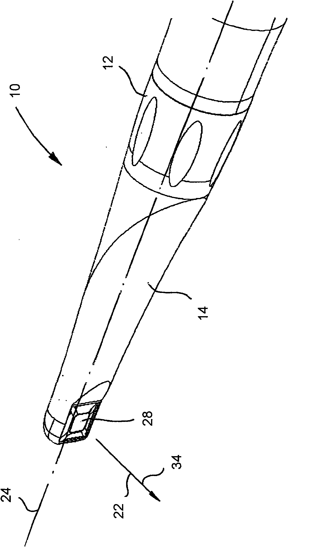
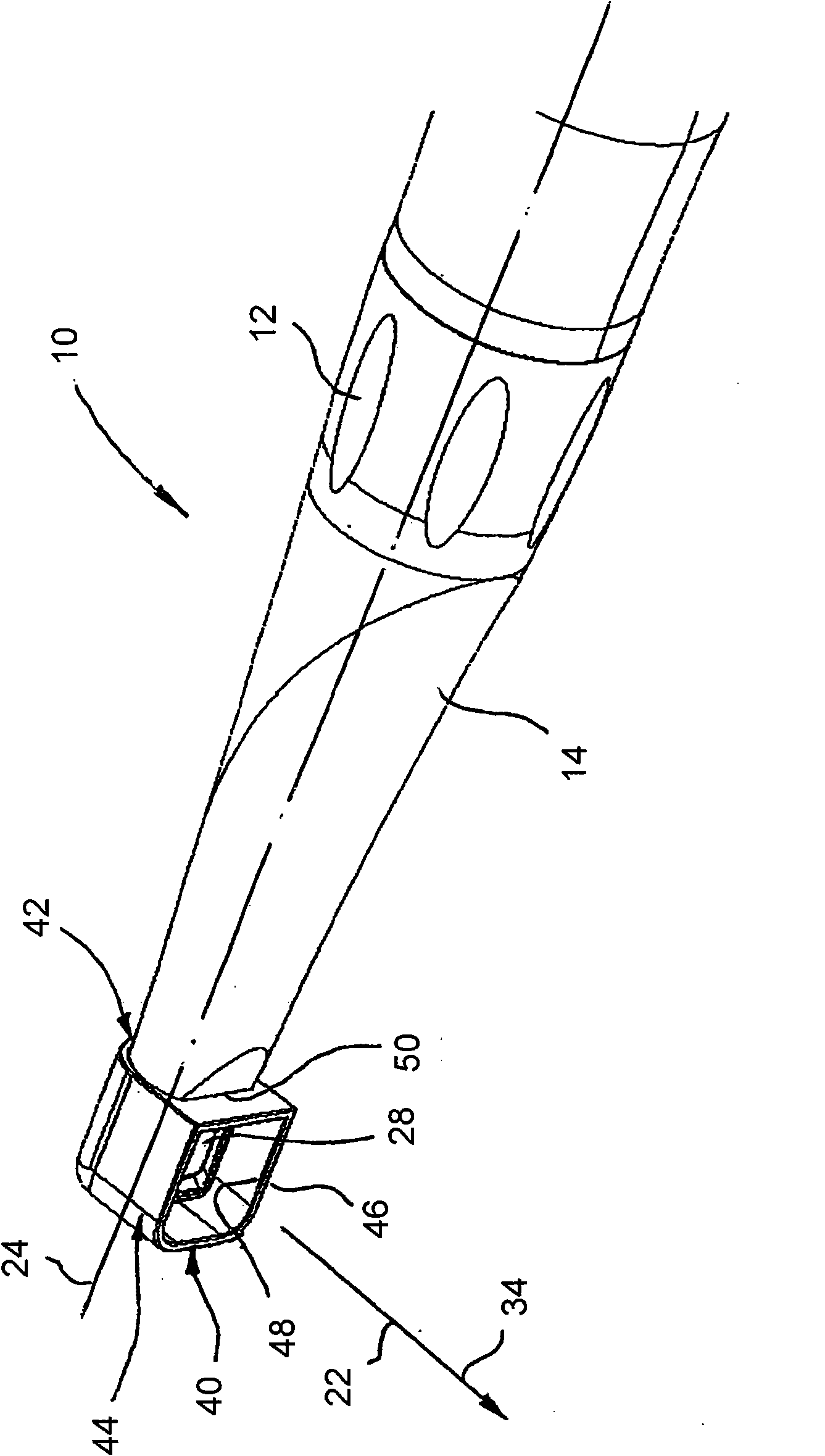
[0031] figure 1 A dental diagnostic camera 10 is shown, which has a handle section 12 and a head region 14 which is substantially designed in the shape of a cone section and which is mounted on the extension of the handle section 12 .

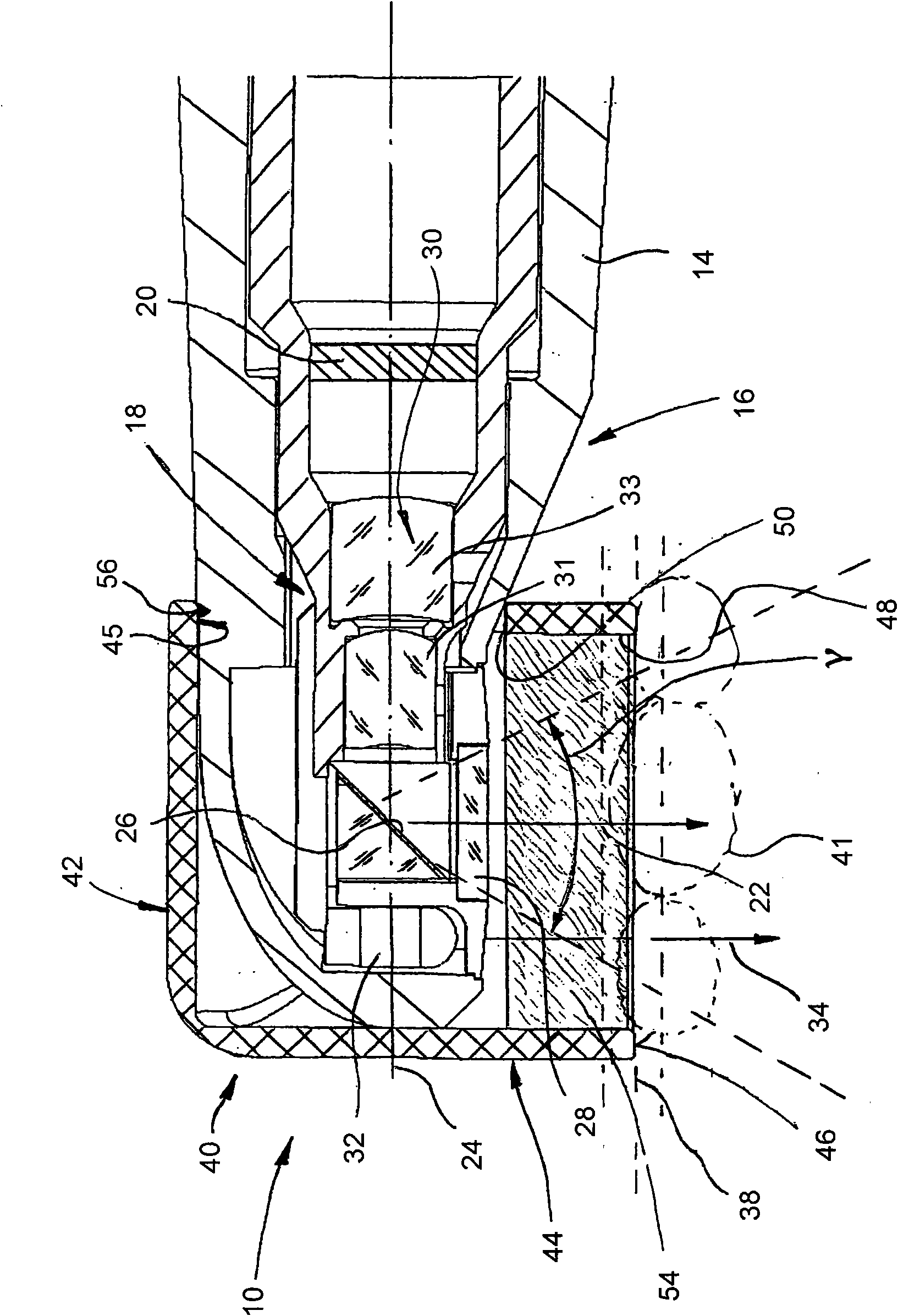
[0032] On the rear end (not shown) of the handle section 12 facing away from the top region 14, the dental diagnostic camera 10 has a cable, not shown, which is used to provide electrical energy and in particular transmit the signals generated by the dental diagnostic camera 10. electrical image signal. The image signal is generated by a camera unit 16 built into the top area 14 .

[0033] Such as image 3 As shown in detail in , the camera unit 16 is mainly composed of an optical system 18 and an imaging unit 20 . The viewing direction 22 of the dental diagnostic camera 10 is substantially perpendicular to the central longitudinal axis of the handle section 21 and the head region 14 . This ensures a particularly ergonomic handling of the d...


PUM


Abstract

An attachment (40, 40a, 40b) for a diagnostic (10) comprises a coupling section (42) configured for the detachable connection to a head region (14) of a diagnostic camera (10), and a dimensionally stable spacer (44) that is connected to said section and has a free end section (46).

Description

technical field [0001] The invention relates to a diagnostic camera and a top cover for realizing the diagnostic camera. Background technique [0002] Known dental diagnostic cameras are used to observe a patient's oral cavity remotely. The housing of the diagnostic camera has a handle section and a thinner head section connected to the handle section. The handle section is used to hold and guide the diagnostic camera by a user. The top area mounted on the extension of the handle section contains a camera unit with optical and electronic components such as optical lenses and a camera. [0003] An image of the oral cavity or teeth to be observed can be captured by the camera unit and transmitted in the form of electrical signals to a playback device such as a monitor. Restricted by working conditions (bending posture, it is difficult to directly see the observation position) it is difficult to capture clear, still, and unambiguous diagnostic camera images of the oral cavit...

Claims


Application Information

Patent Timeline
IPC IPC(8): A61B1/24
CPCA61B1/05A61B1/00089G03B15/03A61B5/6844G03B17/17A61B1/00101A61B1/00177A61B1/00096A61B1/0676A61B5/6886A61B1/0684A61B1/247
Inventor M·汤姆斯P·莱斯
Owner DURR DENTAL GMBH & CO KG
Why Eureka
Try Eureka