
Sight line detector and method for detecting sight line

A line-of-sight detection and line-of-sight technology, which is applied in the field of line-of-sight detection devices, can solve the problems of not being able to photograph immediately, not being able to prompt the photographer to correct graphics, and calculating correction parameters.

Active Publication Date: 2010-03-24
PANASONIC CORP
View PDF4 Cites 24 Cited by
  • Summary
  • Abstract
  • Description
  • Claims
  • Application Information

AI Technical Summary

Problems solved by technology

[0011] In Patent Document 3, since the calibration graph is displayed on the monitor, in a state without a display like a head-mounted camera, the photographer cannot be presented with the calibration graph and cannot acquire the calibration parameters.
[0012] And, in Patent Document 4, the photographer needs to set a target as a feature point in advance, and the target must be reflected in the imaging unit mounted on the head. habit
[0013] In this way, in the prior art described above, preliminary preparations for determining the correction parameters are required and complicated, which not only burdens the photographer, but also makes it difficult to easily calculate the correction parameters if the photographer is not used to the operation.

Method used


Image

  • Sight line detector and method for detecting sight line
  • Sight line detector and method for detecting sight line
  • Sight line detector and method for detecting sight line

Examples


Embodiment Construction

[0066] Hereinafter, embodiments of the present invention will be described with reference to the drawings.

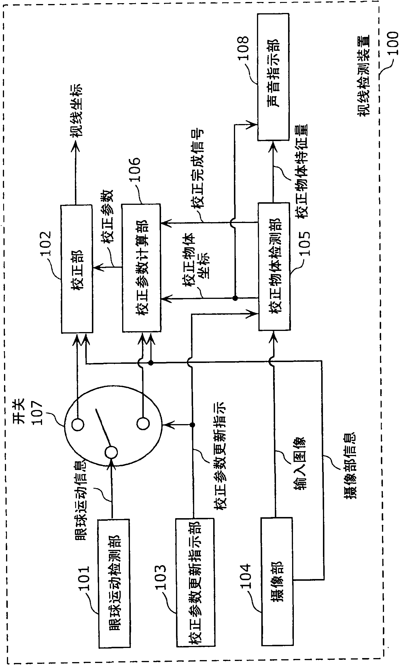
[0067] figure 1 It is a block diagram showing an example of the configuration of the line-of-sight detection device 100 of this embodiment. The line-of-sight detection device 100 shown in the figure includes an eye movement detection unit 101, a correction unit 102, a correction parameter update instruction unit 103, an imaging unit 104, a correction object detection unit 105, a correction parameter calculation unit 106, a switch 107, and an audio instruction unit 108. .

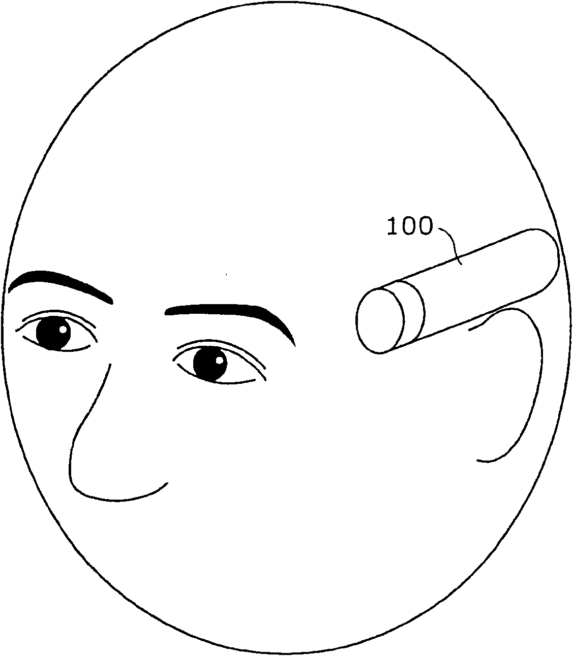
[0068] In addition, the line-of-sight detection device 100 of this embodiment is, for example, figure 2 As shown, it is installed on the photographer's head, and the camera is photographed in the direction of the photographer's line of sight.

[0069] The eye movement detection unit 101 acquires eye movement information by detecting the eye movement of the user (photographer). For example, the ey...


PUM


Abstract

A sight line detector that accurately calculates calibration parameters in a short time to detect sight line coordinates of a person being photographed on the input image from an imaging section mounted on the head of the person being photographed. A sight line detector (100) detects sight line coordinates of a user on the input image from an imaging section (104) mounted on the head of the user.The sight line detector (100) has an ocular movement detection section (101) to detect the ocular movement of the user, a calibration object detection section (105) that acquires the input image to determine whether or not an object available as a calibration object is included on the acquired input image, and that outputs position coordinates indicating a position the object when it is determinedthat such an object is included, an audio instruction section (108) that instructs the user to see the calibration object indicated by the position coordinates, a calibration parameter calculation section (106) to calculate the calibration parameters using the information on the ocular movement of the user receiving the instruction and the position coordinates of the calibration object, and a calibration section (102) to calibrate the information on the ocular movement to the sight line coordinates using the calculated calibration parameters.

Description

technical field [0001] The present invention relates to a line of sight detection device and a line of sight detection method for obtaining the line of sight coordinates of a photographer in an input image from an imaging unit installed on the head of the photographer. Background technique [0002] For example, as disclosed in Patent Document 1, a head-mounted camera has been proposed. By mounting the imaging unit on the head, it has the advantage that both hands become free during photography, and it is possible to perform other tasks while taking pictures. for photography. Furthermore, Patent Document 2 proposes an invention in which stable imaging can be performed without changing the imaging position even if the photographer moves his or her head during imaging by moving the imaging position of the imaging unit according to the photographer's gaze position. [0003] As one of the methods of actually moving the shooting position correctly based on the position of the lin...

Claims


Application Information

Patent Timeline
IPC IPC(8): A61B3/113G03B15/00G06F3/033H04N5/225
CPCG06F3/013G03B2213/025A61B3/113G03B15/00G06V40/19
Inventor 杉尾敏康佐藤大将
Owner PANASONIC CORP
Learn More