Supercharge Your Innovation With Domain-Expert AI Agents!

Implant face plates

A panel and component technology, which is applied in the field of medical transplantation to replace part of human anatomical structures, can solve the problems of vertebral disc loss of support function, vertebral disc fracture, degeneration, etc.

Inactive Publication Date: 2010-03-24
WARSAW ORTHOPEDIC INC
View PDF0 Cites 16 Cited by
  • Summary
  • Abstract
  • Description
  • Claims
  • Application Information

AI Technical Summary

Problems solved by technology

However, due to injury, degeneration, disease, or the like, these discs can rupture, degenerate and / or protrude to such an extent that the intervertebral space between adjacent vertebrae collapses due to the loss of the disc at least Partial support function

Method used


Image

  • Implant face plates
  • Implant face plates
  • Implant face plates

Examples


Embodiment Construction

[0023] In order to facilitate an understanding of the principles of the invention, references are made to the drawings and specific language is used to describe embodiments or examples. It should be understood, however, that no limitation of the scope of the invention is intended. Any alterations and further improvements in the illustrated embodiments, and any further applications of the principles of the invention described herein are contemplated, as would normally occur to one skilled in the art to which this invention pertains.

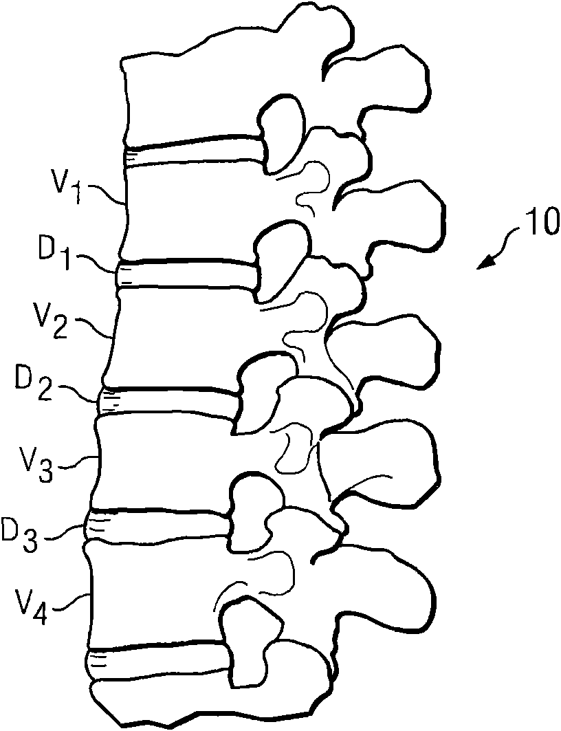
[0024] figure 1 A side view of a portion of the spine 10 is shown showing a set of adjacent upper and lower vertebrae Vl, V2, V3, V4 separated by non-artificial intervertebral discs Dl, D2, D3. The schematic diagrams of the four vertebrae are intended as examples only. Another example is the sacrum and one vertebra.

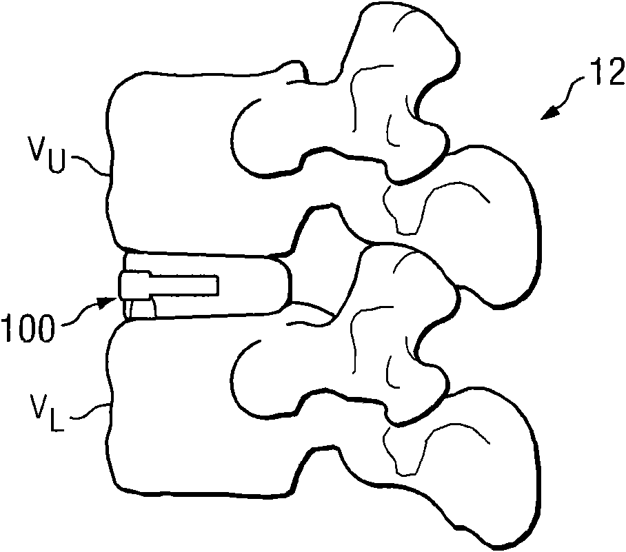
[0025] As a further example, refer to figure 2 The spine segment 12 is shown to illustrate two vertebrae. The upper vertebra ...


PUM


Abstract

A faceplate for at least partially covering a plurality of anchor member apertures in an implantable member includes a main body sized to at least partially overlap the plurality of anchor member apertures of the implantable member and configured to inhibit anchor member back-out from the plurality of anchor member apertures. A locking tab may be associated with the main body, the locking tab being formed to at least partially elastically deform to engage the implantable member and secure the main body in place.

Description

technical field [0001] The present invention relates generally to the field of replacing parts of human anatomy with medical grafts. Background technique [0002] Spinal discs between the endplates of adjacent vertebrae (vertebrae) in the human spine provide critical support. However, due to injury, degeneration, disease, or the like, these discs can rupture, degenerate and / or protrude to such an extent that the intervertebral space between adjacent vertebrae collapses due to the loss of the disc at least Some support functions. This can cause nerve root shock and neuralgia. In some cases, surgical correction may be required. [0003] Some surgical corrections involve the removal of a natural spinal disc from between adjacent vertebrae. To preserve disc space for normal spinal function, graft elements may be inserted between adjacent vertebrae. [0004] Certain graft elements employ anchor elements that hold the graft element in place between adjacent vertebrae. Over t...

Claims


Application Information

Patent Timeline
IPC IPC(8): A61F2/44A61F2/30A61F2/46
CPCA61F2/28A61F2220/0041A61F2002/30604A61F2002/3008A61F2220/0025A61F2310/00329A61F2/447A61B17/86A61F2002/30354A61F2002/2817A61F2002/30787A61F2002/30904A61F2002/30507A61F2002/30439A61F2002/30062A61B17/8033A61F2002/4475A61F2002/30841A61F2250/0098A61F2/30721A61F2310/00029A61F2002/30517A61F2310/00293A61F2310/00179A61F2002/30131A61F2002/30777A61F2002/30828A61F2310/00017A61F2/4611A61F2310/00023A61F2210/0004A61F2220/0033A61F2002/2835A61F2230/0013A61F2310/00359A61F2002/30433A61F2002/30593
Inventor L·G·沃戈J·A·艾迪M·D·舒尔茨
Owner WARSAW ORTHOPEDIC INC
Features
  • R&D
  • Intellectual Property
  • Life Sciences
  • Materials
  • Tech Scout
  • Unparalleled Data Quality
  • Higher Quality Content
  • 60% Fewer Hallucinations
Learn More