
Tape drive

A driving device, driving belt technology, applied in the direction of inking device, non-electric variable control, comparison unit, etc., can solve problems such as difficult to obtain performance, and achieve the effect of large acceleration and deceleration, simple mechanical assembly

Active Publication Date: 2010-03-24
ZIPHER
View PDF2 Cites 12 Cited by
  • Summary
  • Abstract
  • Description
  • Claims
  • Application Information

AI Technical Summary

Problems solved by technology

[0014] [14] The requirements of high-speed transfer printers for the deceleration, acceleration, speed and positioning accuracy of the belt make it difficult for many known drive mechanisms to obtain acceptable performance under high reliability conditions
Similar restrictions are imposed in applications other than high-speed printers, such as drives used in label printers adapted to use labels separated from label sheets

Method used


Image

  • Tape drive
  • Tape drive

Examples


Embodiment Construction

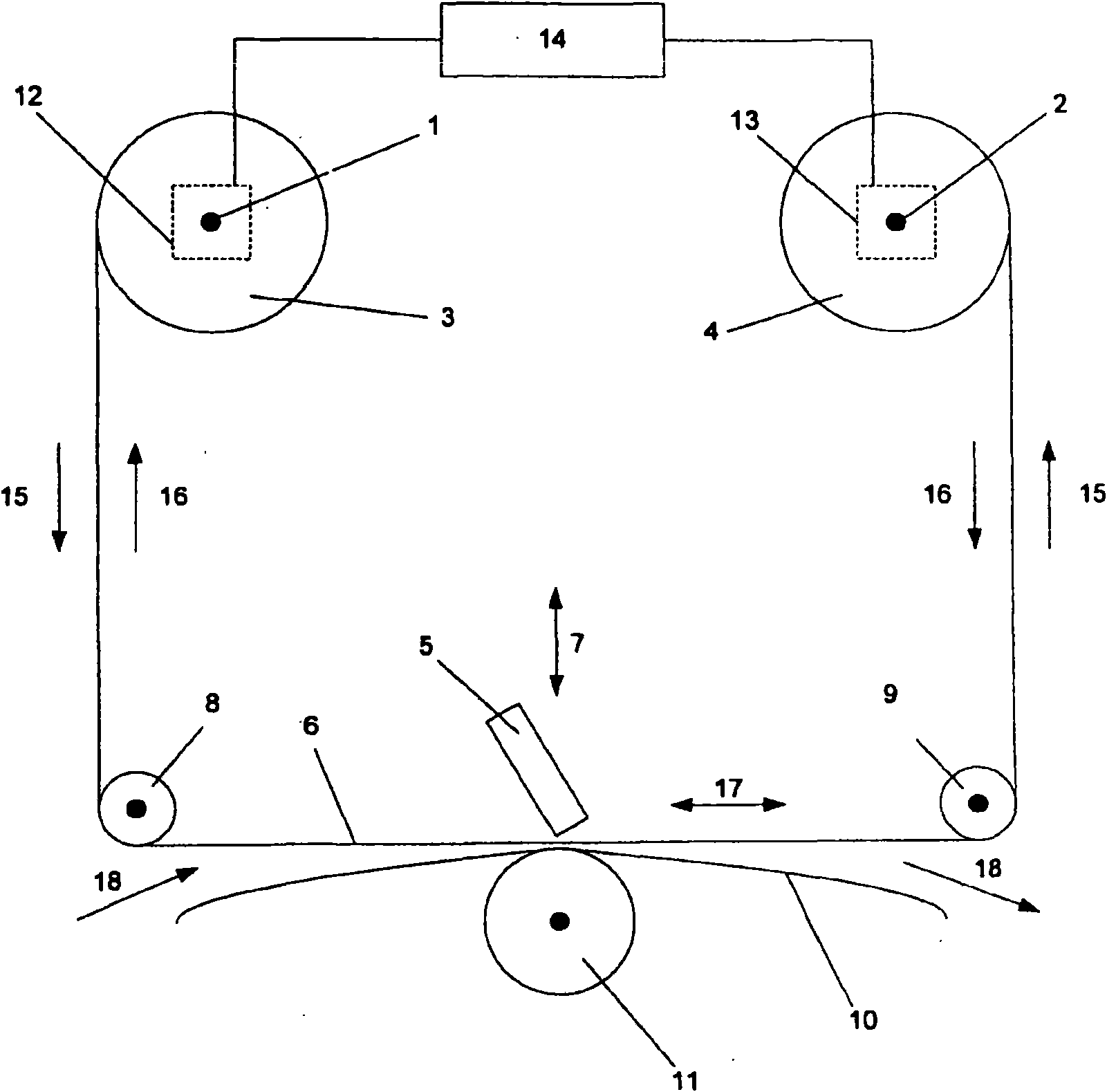
[0029] [29] cf. figure 1 , which schematically illustrates a belt drive suitable for use in a thermal transfer printer according to the present invention. The first shaft 1 and the second shaft 2 support a supply reel 3 and a take-up reel 4, respectively. The supply reel 3 is initially wound with a roll of unused tape, while the take-up reel 4 is initially not carrying any tape. As the tape is used, the used portion of the tape is transferred from the supply reel 3 to the take-up reel 4 . A movable print head 5 is provided which is movable relative to the belt 6 at least in a first direction indicated by arrow 7 . Belt 6 extends from supply reel 3 to take-up reel 4 around rollers 8 , 9 . The path followed by the belt 6 between the rollers 8 and 9 passes in front of the print head 5 . The substrate 10 on which the printed pattern is deposited comes into contact with the belt 6 between the rollers 8 and 9 and the belt 6 is inserted between the print head 5 and the substrate ...


PUM


Abstract

The invention relates to a tape drive comprising two position-controlled motors (12, 13), at least one of which is a closed-loop position-controlled motor, two tape spool supports on which spools (3, 4) of tape may be mounted, each spool being drivable by a respective one of said motors, and a controller (14) for controlling the energisation of the motors such that the tape may be transported in at least one direction between spools mounted on the spool supports. The controller is operative to energise both motors to drive the spools of tape in the direction of tape transport, to monitor tension in a tape being transported between spools mounted on the spool supports and to control the motors to maintain the monitored -tension between predetermined limits.

Description

technical field [0001] [1] The present invention relates to a belt drive device. Such a tape drive may form part of a printing apparatus. In particular, such a belt drive may be used in transfer printers, ie printers that use ink carried by a carrier. Background technique [0002] [2] In transfer printers, a belt that is commonly called a printer belt and that carries ink on one side is set inside the printer so that the printhead can contact the other side of the belt so that ink can be transferred from the belt to, for example, Paper or flexible film target substrates. Such printers are used in many applications. Industrial printing applications include thermal transfer label printers and thermal transfer encoders, which print directly onto substrates such as packaging materials made from flexible films or cards. [0003] [3] Ink ribbon is typically delivered to the end user in the form of a roll wound onto a core. The end user pushes the core onto the spool and pulls...

Claims


Application Information

Patent Timeline
Patent Type & Authority Applications(China)
IPC IPC(8): B41J33/34
CPCB41J33/34G11B15/46G11B15/43G05B1/01G05B13/02G05D15/01
Inventor 马丁·莫西奈斯瑞基思·布克斯顿乔治·鲍尔基·芸德特
Owner ZIPHER
Learn More