
Pneumatic tire

A technology of pneumatic tires and tires, applied in the direction of pneumatic tires, special tires, tire parts, etc., can solve the problems of large lateral resistance, comfort that cannot be said to meet the requirements, and cannot be increased

Inactive Publication Date: 2010-03-24
BRIDGESTONE CORP
View PDF3 Cites 7 Cited by
  • Summary
  • Abstract
  • Description
  • Claims
  • Application Information

AI Technical Summary

Problems solved by technology

[0010] However, in the above-mentioned first and third conventional examples, since a large cornering force cannot be generated when turning, it is not possible to improve steering stability, etc.
In addition, in the above-mentioned second conventional example, although the lateral resistance force at the time of turning can be increased compared with the first and third conventional examples, it cannot be greatly increased.
In addition, the vibration absorption characteristics and shock absorption cannot be improved, and it cannot be said that it can meet the requirements in terms of comfort.
[0011] In addition, in addition to the first and second conventional examples, various asymmetrical pneumatic tires have been proposed, but none have been proposed that can simultaneously satisfy steering stability. Pneumatic tires with comfort (riding comfort, quietness)

Method used


Image

  • Pneumatic tire
  • Pneumatic tire
  • Pneumatic tire

Examples


Embodiment

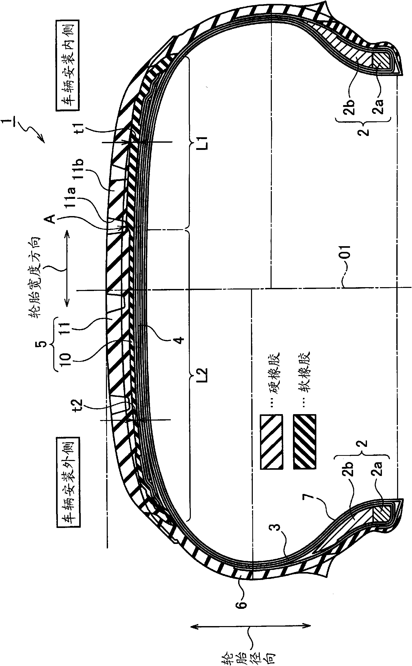
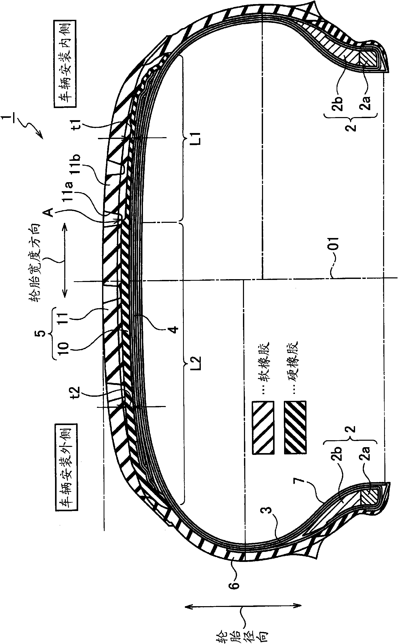
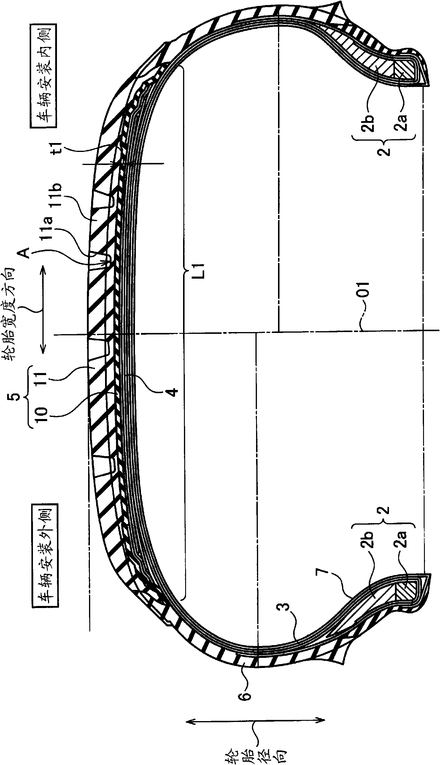
[0051] Next, a comparative experiment to prove the effect of the pneumatic tire of the present invention was performed and described here. The tires used in the experiment were the tires of Examples 1 to 4, the tires of Conventional Examples, and the tires of Comparative Examples 1 to 5 which realized the above-mentioned embodiment. The size of each tire is 225 / 55R17, the rim size is 7.5J×17, and the tire internal pressure is 220 kPa. The test vehicle was Toyota's CELSIOR (trade name), and the number of passengers was 2 (load).

[0052] Such as Figure 4 As shown, in the tire of the conventional example, the tread portion is composed of two layers of rubber, and the thicknesses of the cap rubber and the base rubber are constant over the entire tread. In the tires of Examples 1 and 2 and the tires of Comparative Examples 1 to 3, the tread portion is composed of two layers of rubber, and the tread portion is divided into two sections, the inner section L1 and the outer section...


PUM


Abstract

The outside and inside at mounting on a vehicle are designated.A tread section (5) consists of a base rubber layer (10) laid inside in the radial direction of the tire and a cap rubber layer (11) laidoutside in the radial direction of the tire. The base rubber layer (10) consists of a rubber of storage elasticity modulus lower than that of the cap rubber layer (11). The thickness (t1) of the baserubber layer (10) is large in the zone (L1) of inside at vehicle mounting from a boundary location (A) being an arbitrary location in the tire width direction of the tread section while the thickness(t2) of the base rubber layer (10) is small in the zone (L2) of the outside therefrom.

Description

technical field [0001] The present invention relates to a pneumatic tire whose outer side and inner side when mounted on a vehicle are specified. Background technique [0002] In recent years, as the demand for improvement in the performance of pneumatic tires has increased, there has been an increasing need for technologies that simultaneously achieve mutually opposite performances such as steering stability, comfort (riding comfort, quietness), and wear resistance. As one of these techniques, a pneumatic tire has been proposed that is asymmetrical with respect to the equatorial plane of the tire. [0003] In the use environment of this kind of pneumatic tire installed on the vehicle, the input of the suspension condition, positioning, and self-driving plane to the pneumatic tire is asymmetrical with respect to the equatorial plane of the tire. The force acting on the pneumatic tire and the functional requirements that the pneumatic tire should undertake are still asymmetr...

Claims


Application Information

Patent Timeline
Patent Type & Authority Applications(China)
IPC IPC(8): B60C11/00B60C5/00
CPCB60C11/005B60C3/06B60C2011/0025B60C11/0304B60C11/00B60C11/0066
Inventor 永井秀
Owner BRIDGESTONE CORP
Learn More