Dual-type wave gear device

A technology of wave gears and gears, applied in gear transmissions, transmissions, belts/chains/gears, etc., to achieve the effects of eliminating insufficient meshing, good meshing state, and increasing average pressure angle

Active Publication Date: 2017-03-22
HARMONIC DRIVE SYST IND CO LTD
View PDF9 Cites 2 Cited by
  • Summary
  • Abstract
  • Description
  • Claims
  • Application Information

AI Technical Summary

Problems solved by technology

In addition, Patent Document 5 describes that the thickness of the rim of the ext

Method used


Image

  • Dual-type wave gear device
  • Dual-type wave gear device
  • Dual-type wave gear device

Examples


Embodiment Construction

[0066] Hereinafter, embodiments of a duplex wave gear device to which the present invention is applied will be described with reference to the drawings.

[0067] [Overall configuration of the wave gear unit]

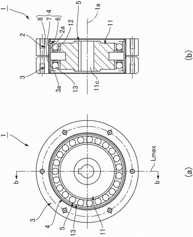
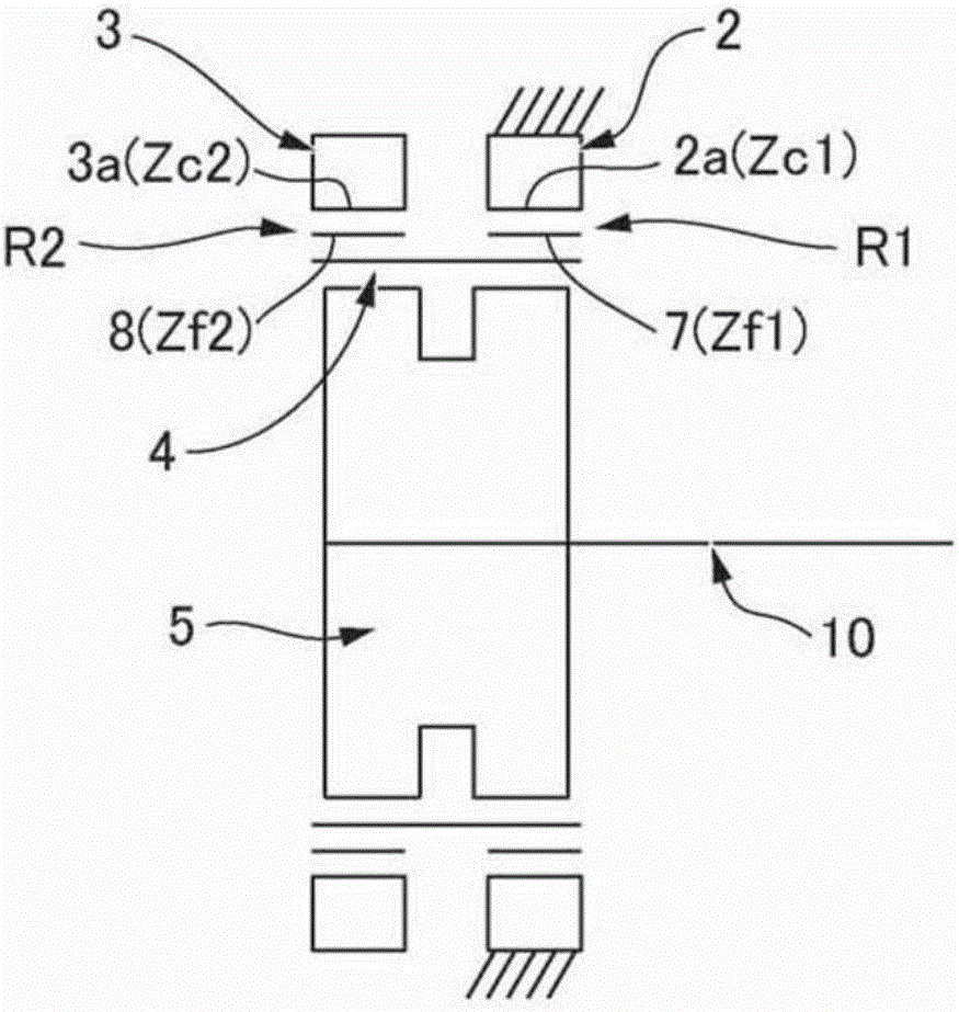
[0068] figure 1 It is an end view and a longitudinal sectional view showing a dual type wave gear device (hereinafter, simply referred to as a "wave gear device") according to an embodiment of the present invention, figure 2 is its schematic diagram. The wave gear device 1 is used as, for example, a speed reducer, and includes: an annular rigid first internal gear 2, an annular rigid second internal gear 3, and a thin elastic body capable of bending deformation in the radial direction. A flexible external tooth gear 4 in a cylindrical shape and a wave generator 5 with an elliptical profile are formed.

[0069] The first and second internally toothed gears 2 and 3 are coaxially arranged in parallel with a predetermined gap in the direction of the center axis 1a. In t...


PUM


Abstract

An externally toothed gear of a dual-type wave gear device is provided with first and second external teeth (7, 8) having different teeth numbers. The first and second external teeth (7, 8) are bent by a wave generator by the same bending amount, into an elliptical shape. The tooth depth (h1) of tooth profiles (70) of the first external teeth (7) having a low teeth number is smaller than the tooth depth (h2) of tooth profiles (80) of the second external teeth (8) having a high teeth number. Accordingly, a dual-type wave gear device can be achieved with which the first and second external teeth having different teeth numbers can be suitably bent to form excellent mating states with respective internally toothed gears.

Description

technical field [0001] The present invention relates to a wave gear device including a pair of internal gears, a cylindrical external gear capable of bending deformation in the radial direction, and a wave generator. Background technique [0002] A wave gear device equipped with a cylindrical external gear generally includes: a stationary side internal gear that is fixed and does not rotate, a wave generator as a rotation input element, a driving side internal gear as a deceleration rotation output element, and a A cylindrical external gear that meshes with the stationary internal gear and the drive internal gear and is capable of bending deformation in the radial direction. In a typical wave gear device, the externally toothed gear is bent and deformed into an elliptical shape, and the positions at both ends of the major axis of the elliptical shape can mesh with the internal gears on the stationary side and the driving side. [0003] Patent Documents 1 and 5 describe gene...

Claims


Application Information

Patent Timeline
IPC IPC(8): F16H1/32
CPCF16H1/32F16H49/001F16H2049/003F16H55/16
Inventor 清泽芳秀半田纯张新月泷泽登
Owner HARMONIC DRIVE SYST IND CO LTD
Why Eureka
Try Eureka