Plasma display panel

A display panel and plasma technology, applied in AC plasma display panels, gas discharge electrodes, gas discharge tubes/containers, etc., can solve problems such as increased attenuation rate

Inactive Publication Date: 2010-03-24
PANASONIC CORP
View PDF4 Cites 2 Cited by
  • Summary
  • Abstract
  • Description
  • Claims
  • Application Information

AI Technical Summary

Problems solved by technology

However, when impurities are mixed into the protective layer to improve the electron emission characteristics, charges are accumulated on the surface of the

Method used


Image

  • Plasma display panel
  • Plasma display panel
  • Plasma display panel

Examples


Embodiment approach

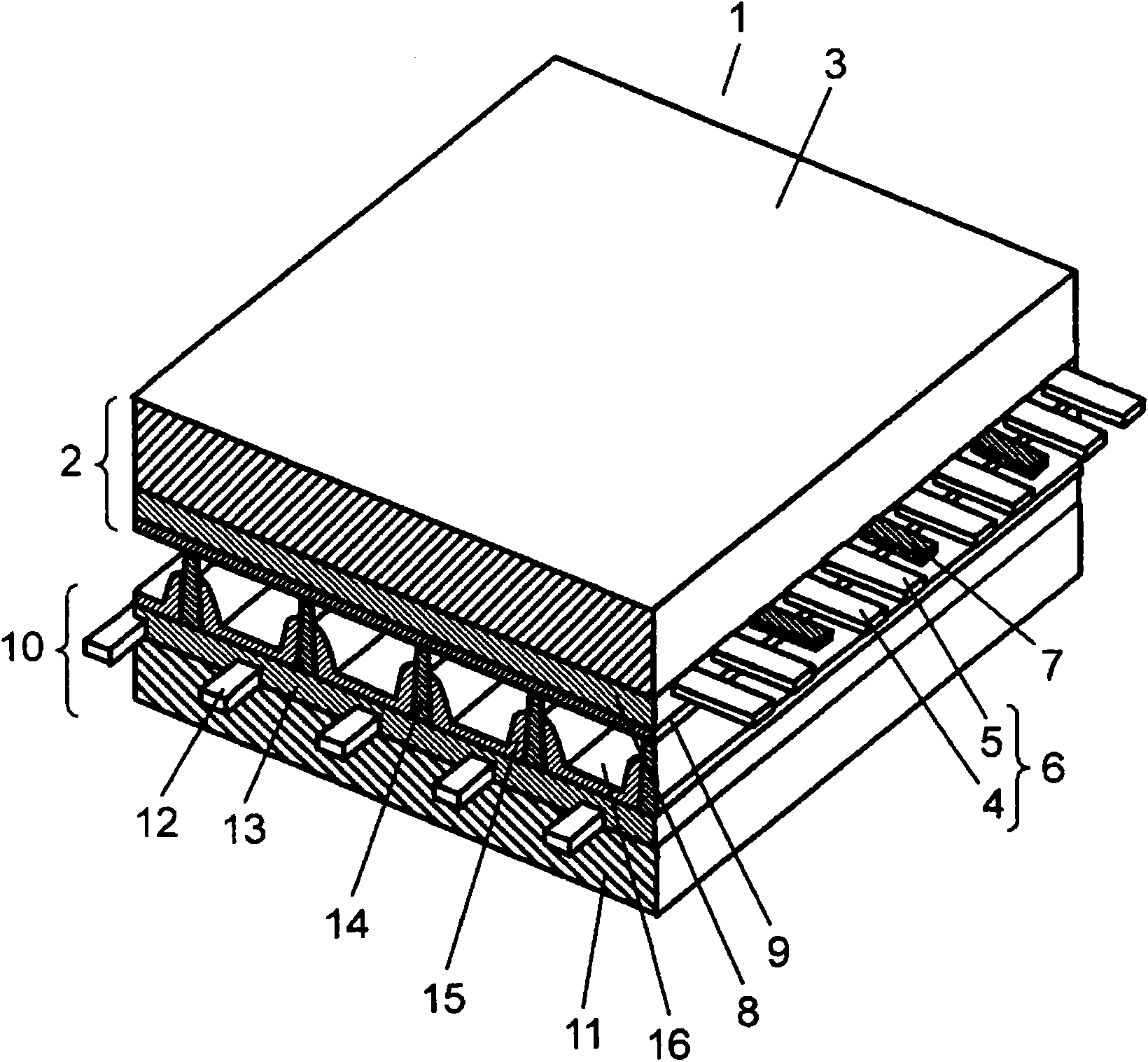
[0028] figure 1 It is a perspective view showing the structure of the PDP according to the embodiment of the present invention. The basic structure of the PDP is the same as that of a general AC surface discharge type PDP. Such as figure 1 As shown, the PDP 1 is disposed facing a front panel 2 composed of a front glass substrate 3 and the like and a rear panel 10 composed of a rear glass substrate 11 and the like. The outer peripheral portion of the PDP 1 is sealed with a sealing material made of glass frit or the like. In the discharge space 16 inside the sealed PDP 1 , discharge gases such as Ne and Xe are sealed under a pressure of 400 Torr to 600 Torr.

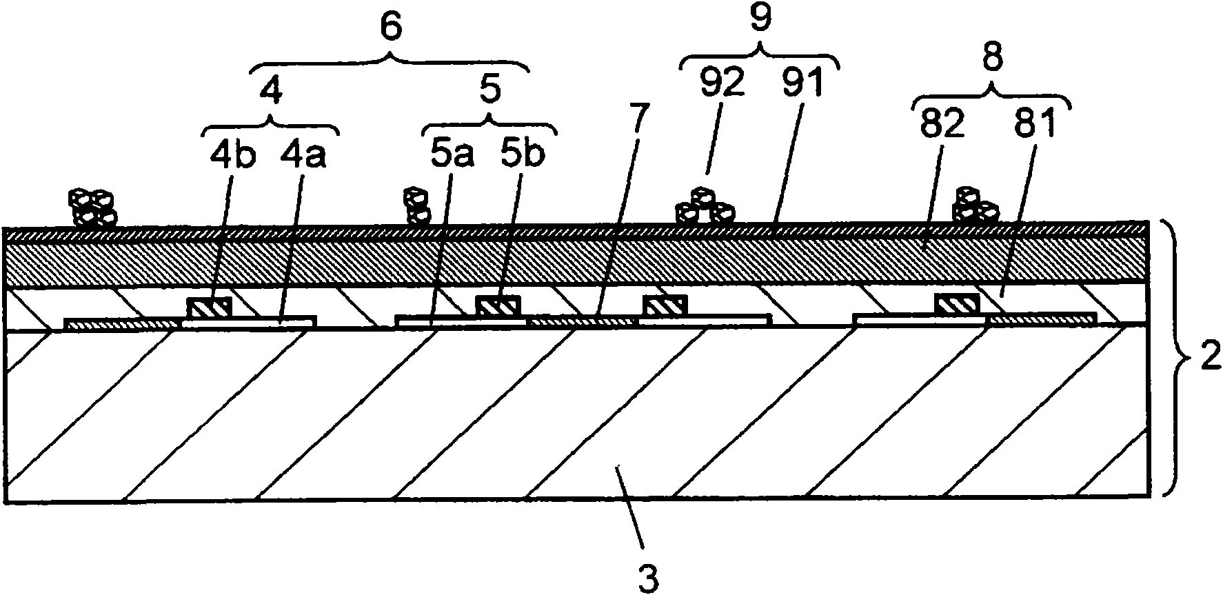
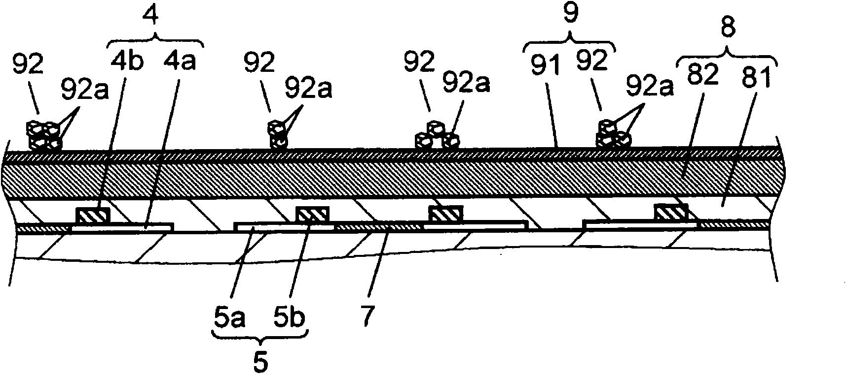
[0029] On front glass substrate 3 of front panel 2, a pair of strip-shaped display electrodes 6 and black strips (light shielding layers) 7 composed of scan electrodes 4 and sustain electrodes 5 are arranged in parallel to each other. On the front glass substrate 3, a dielectric layer 8 covering the display electrodes ...


PUM

PropertyMeasurementUnit
The average particle sizeaaaaaaaaaa

Abstract

Disclosed is a plasma display panel comprising a front plate (2) wherein a dielectric layer (8) is so formed as to cover a display electrode (6) formed on a front glass substrate (3) and a protectivelayer (9) is formed on the dielectric layer (8), and a back plate so arranged as to face the front plate (2) so that a discharge space is formed therebetween. The back plate is provided with an address electrode lying in the direction intersecting the display electrode (6) and a partition wall which divides the discharge space. The protective layer (9) is obtained by forming a base film (91) composed of MgO on the dielectric layer (8), and having agglomerated particles (92), wherein a plurality of crystal particles composed of a metal oxide are agglomerated, adhere to the base film (91) in such a manner that the agglomerated particles (92) are distributed all over the base film (91). The base film (91) contains Si as a raw material impurity, and the Si concentration is set at more than 0 ppm but not more than 10 ppm.

Description

technical field [0001] The present invention relates to a plasma display panel used for a display device or the like. Background technique [0002] Plasma display panels (hereinafter referred to as "PDP") are commercialized as 65-inch televisions and the like because they can achieve high definition and large screen size. In recent years, the application of PDPs to high-definition televisions with twice or more scanning lines compared with the conventional NTSC system has been promoted, and PDPs containing no lead components are required in consideration of environmental issues. [0003] The PDP is mainly composed of a front panel and a rear panel. The front panel is composed of the following parts: a glass substrate of sodium borosilicate glass based on the flotation method; a display electrode composed of a strip-shaped transparent electrode and a bus electrode formed on one main surface of the glass substrate; an overlay display Electrodes and a dielectric layer functio...

Claims


Application Information

Patent Timeline
IPC IPC(8): H01J11/02H01J11/12H01J11/22H01J11/24H01J11/26H01J11/34H01J11/36H01J11/38H01J11/40H01J11/42H01J11/44H01J11/50
CPCH01J11/40H01J11/12
Inventor 沟上要河原崎秀司大江良尚
Owner PANASONIC CORP
Why Eureka
Try Eureka