Transmission of system information

A system information, downlink technology, applied in the field of wireless communication networks, which can solve problems such as frequent repetition

Active Publication Date: 2010-03-24
TELEFON AB LM ERICSSON (PUBL)
View PDF0 Cites 10 Cited by
  • Summary
  • Abstract
  • Description
  • Claims
  • Application Information

AI Technical Summary

Problems solved by technology

However, different parts of the dynamic part of the system information are more or less time-critical in the s

Method used


Image

  • Transmission of system information
  • Transmission of system information
  • Transmission of system information

Examples


Embodiment Construction

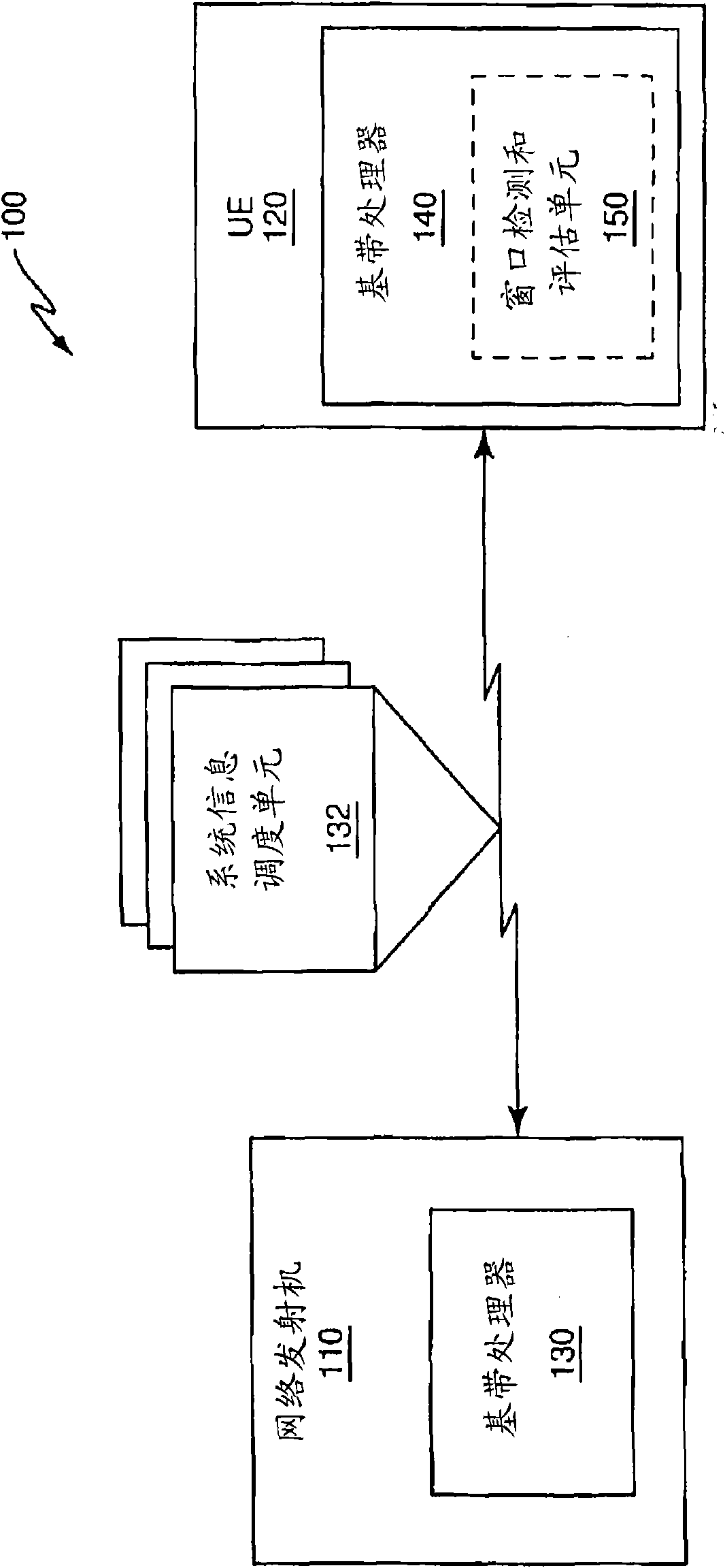
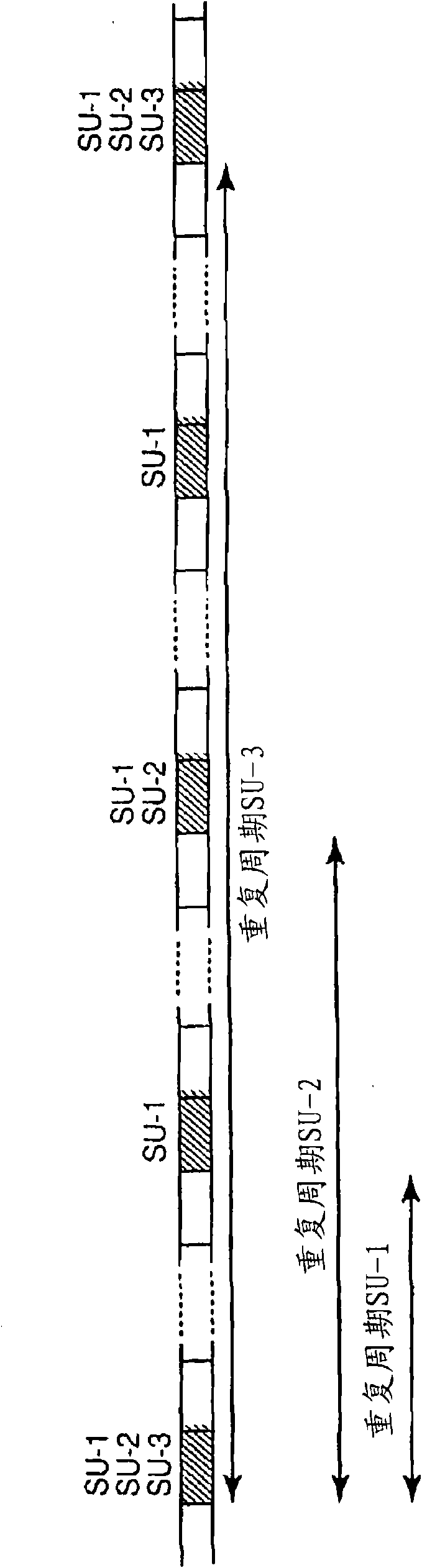
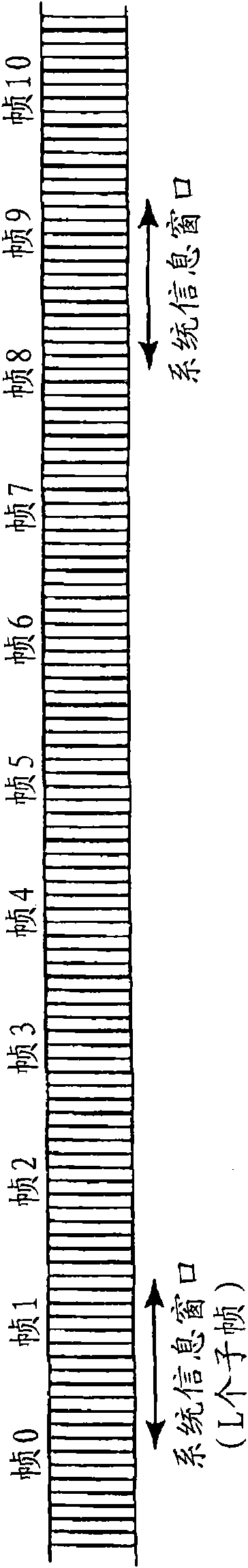
[0017] figure 1 An embodiment of a wireless network 100 comprising one or more network transmitters 110 , such as radio base stations serving one or more UEs 120 , is illustrated. The network transmitter 110 includes a baseband processor 130 for generating one or more scheduling elements 132 (also referred to as system information messages) comprising dynamic portions of system information. The network transmitter 110 sends the scheduling unit 132 to the UE 120 using a different system information window. In one embodiment, the system information window is displayed with the figure 2 The period corresponding to the repetition period of the most frequently occurring scheduling unit 132 is shown, where "SU-n" refers to the nth scheduling unit 132 . The system information corresponding to the most frequently occurring scheduling units 132 is transmitted in each system-information window, while the less frequently occurring scheduling units 132 are transmitted only in a subset ...


PUM


Abstract

In one embodiment, a method of transmitting system information on a down link shared channel structured as successive subframes includes transmitting (400 - 416) system information in regularly occurring time windows, each time window spanning some number of successive subframes. The method further includes indicating (406 / 408) to receiving user equipment (120) which subframes within a given time window carry system information. The method and variations thereof are applied, for example, to the transmission of dynamic system information on the down link shared channel or other down link channel in a 3GPP E-UTRA wireless communication network (100).

Description

technical field [0001] The present invention relates generally to wireless communication networks, and in particular to the transmission of system information to user equipment (UE) operating in such networks, for example by means of the 3GPP E-UTRA (Evolved Universal Terrestrial Radio Access) standard (also referred to as System information is transmitted by radio base stations in a wireless communication network called 3GPP LTE (Long Term Evolution) configuration. Background technique [0002] In 3GPP LTE, downlink user data transmission occurs on the downlink shared channel (DL-SCH) transport channel. In LTE, the time dimension is divided into radio frames of length 10 ms, where each radio frame consists of 10 subframes, each subframe of length 1 ms corresponds to 14 OFDM (Orthogonal Frequency Division Multiplexing) symbols. Each subframe consists of two slots, each of length 0.5 ms or seven OFDM symbols. Note that in case of time division duplex (TDD), only a subset of...

Claims


Application Information

Patent Timeline
IPC IPC(8): H04L1/08
CPCH04L2001/0093H04L1/08H04W48/12
Inventor E·达尔曼V·沃卡洛维克
Owner TELEFON AB LM ERICSSON (PUBL)
Why Eureka
Try Eureka