Automatic placement machine for placing electrical and/or optical components on substrates

A technology of electrical components and optical components, applied in the direction of electrical components, electrical components, etc.

Active Publication Date: 2010-03-24
ASM ASSEMBLY SYST GMBH & CO
View PDF8 Cites 7 Cited by
  • Summary
  • Abstract
  • Description
  • Claims
  • Application Information

AI Technical Summary

Problems solved by technology

[0005] A disadvantage of the prior art is that the user, when he decides on a machine type, often only has very limited options for adapting the automatic assembly machine to possibly changed product parameters in the event of a product change, and New products may therefore have to be produced under more unfavorable conditions

Method used


Image

  • Automatic placement machine for placing electrical and/or optical components on substrates
  • Automatic placement machine for placing electrical and/or optical components on substrates
  • Automatic placement machine for placing electrical and/or optical components on substrates

Examples


Embodiment Construction

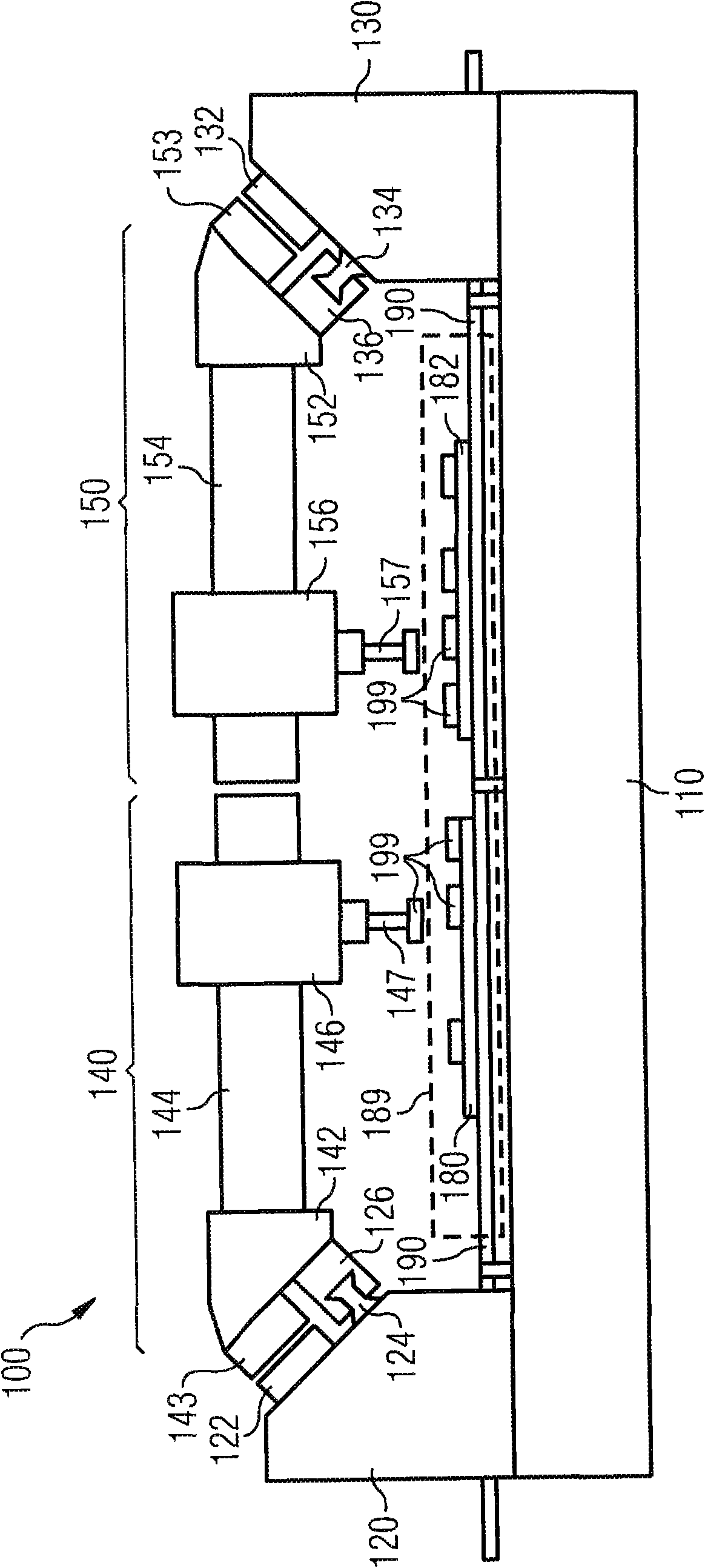
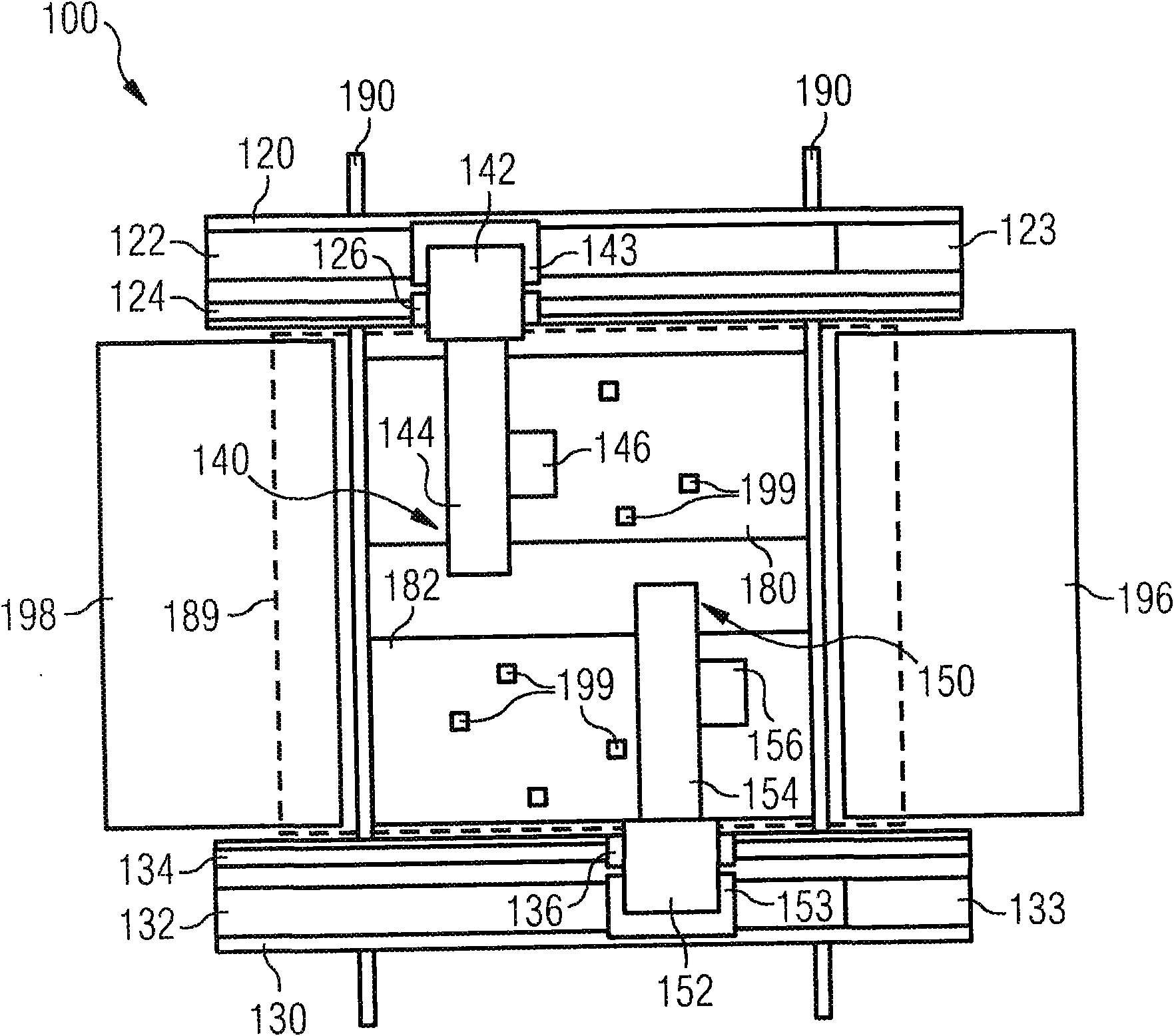
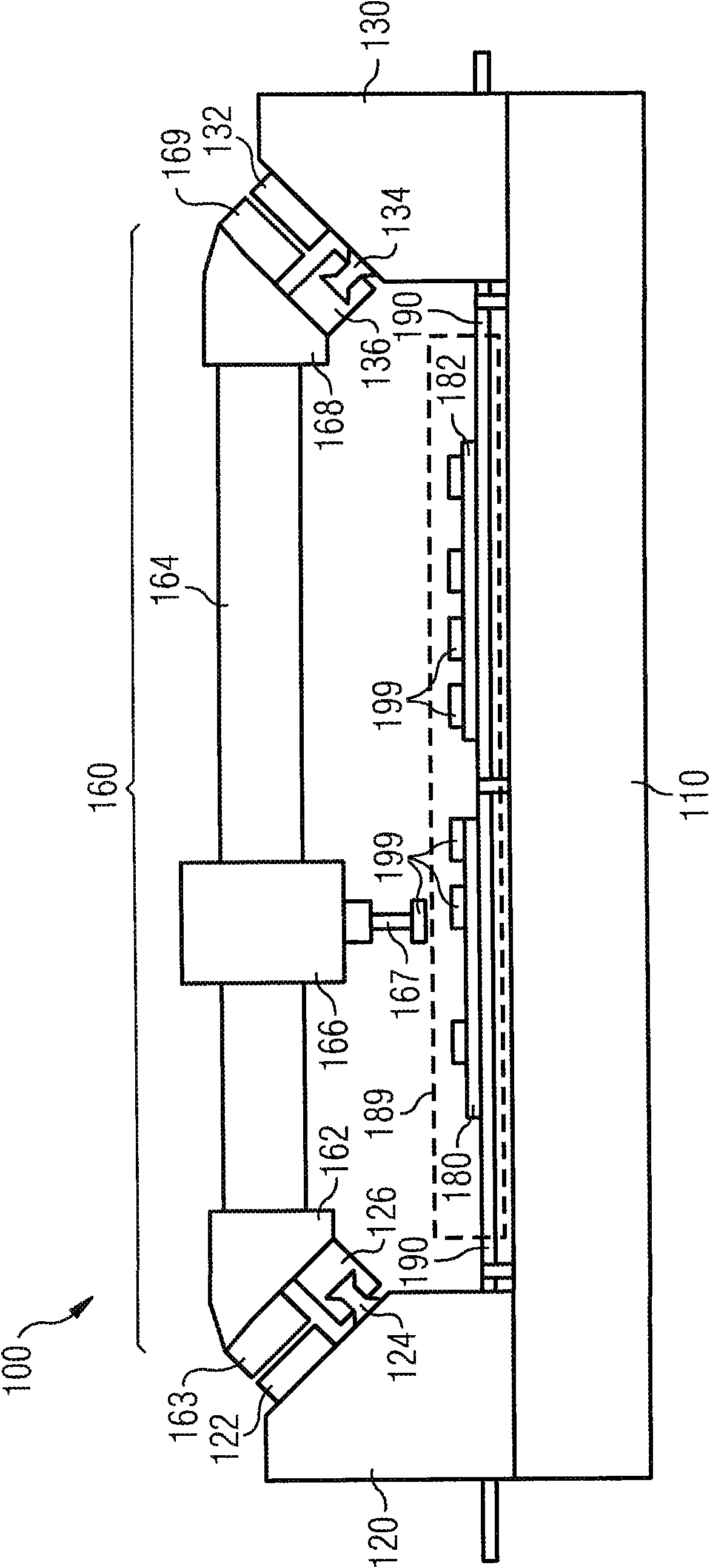
[0092] figure 1 An automatic assembly machine 100 is shown with a base unit 110 and two stands 120 , 130 . Guide rails 124 , 134 are respectively fixed on the brackets for guiding the door frame mounted on the automatic assembly machine 100 . In addition, magnetic rails 122 , 132 are installed on the brackets 120 , 130 respectively, which are used to drive the door frame of the automatic assembly machine 100 .

[0093] The automatic assembly machine 100 has a first door shelf unit 140 which is in figure 1 is shown in the left portion of the automatic assembly machine 100 . The first portal subunit 140 , which is also referred to below as first stub portal 140 , has an assembly head 146 with a suction duct 147 for picking up, transporting and setting down components 199 . The drive of the first cropping gantry 140 takes place via a linear motor drive unit 143 mounted on the gantry head 142 of the cropping gantry 140 and interacting with the left-hand magnetic rail 122 . The...


PUM


Abstract

The invention relates to an automatic placement system for equipping substrates (180, 182, 280, 281, 282, 283) with electrical and / or optical components (199, 299), comprising a base unit, the base unit having a first and a second longitudinally running support (120, 130, 220, 230), arranged essentially in parallel and a placement region (189, (289) arranged between the first and the second support for preparing at least one substrate to be equipped with electrical and / or optical components and a first portal unit (160, 260), with a portal arm (164, 264) guided on both sides and with a placinghead (166, 266) movably attached thereto for equipping a substrate in the placement region. The portal arm (164, 264) guided on both sides is guided and / or mounted at the end regions thereof to the first and the second support (120, 130, 220, 230) and a second portal unit with a single-sidedly guided portal arm (144, 244) and a placement head (146, 246) movably attached thereto for equipping a substrate in the placement region, wherein the single-sidedly guided portal arm (144, 244) is guided in an end region on the first support (120, 220) and the first portal unit ad the second portal unitare interchangeable.

Description

technical field [0001] The invention relates to an automatic assembly machine for assembling electrical and / or optical components on substrates, comprising: a base unit, wherein the base unit has substantially parallel first and second longitudinally extending supports and located between the first and The mounting area between the second brackets is used to provide at least one substrate to be mounted with electrical components and / or optical components, and also includes: a first gantry unit with a gantry arm and a movably fixed thereon An assembly head for assembling the substrate located in the assembly area. Background technique [0002] Such automatic assembly machines are already known from the prior art. For example, US Pat. No. 5,002,448 discloses an automatic assembly machine with two parallel longitudinally extending supports and two portals, each of which is guided on both sides on guide rails, which are respectively fixed on the supports . On each of the gant...

Claims


Application Information

Patent Timeline
IPC IPC(8): H05K13/04
CPCH05K13/0452H05K13/0411H05K13/0404
Inventor 穆罕默德·迈赫迪安普维尔纳·米勒
Owner ASM ASSEMBLY SYST GMBH & CO
Why Eureka
Try Eureka