Separator and flowmeter assembly with same

A separator and flow meter technology, applied in the liquid separation and gas fields, can solve the problems of high price, large volume of separation equipment, complicated adjustment and maintenance work, etc., and achieve the effects of low cost, simple structure and convenient maintenance.

Inactive Publication Date: 2010-03-31
北京宝狮油田设备有限公司 +2
View PDF0 Cites 12 Cited by
  • Summary
  • Abstract
  • Description
  • Claims
  • Application Information

AI Technical Summary

Problems solved by technology

But the disadvantage is that the separation equipment is bulky and expensive, and special metering stations and test pipelines need to be established; moreover, wh

Method used


Image

  • Separator and flowmeter assembly with same
  • Separator and flowmeter assembly with same
  • Separator and flowmeter assembly with same

Examples


Embodiment Construction

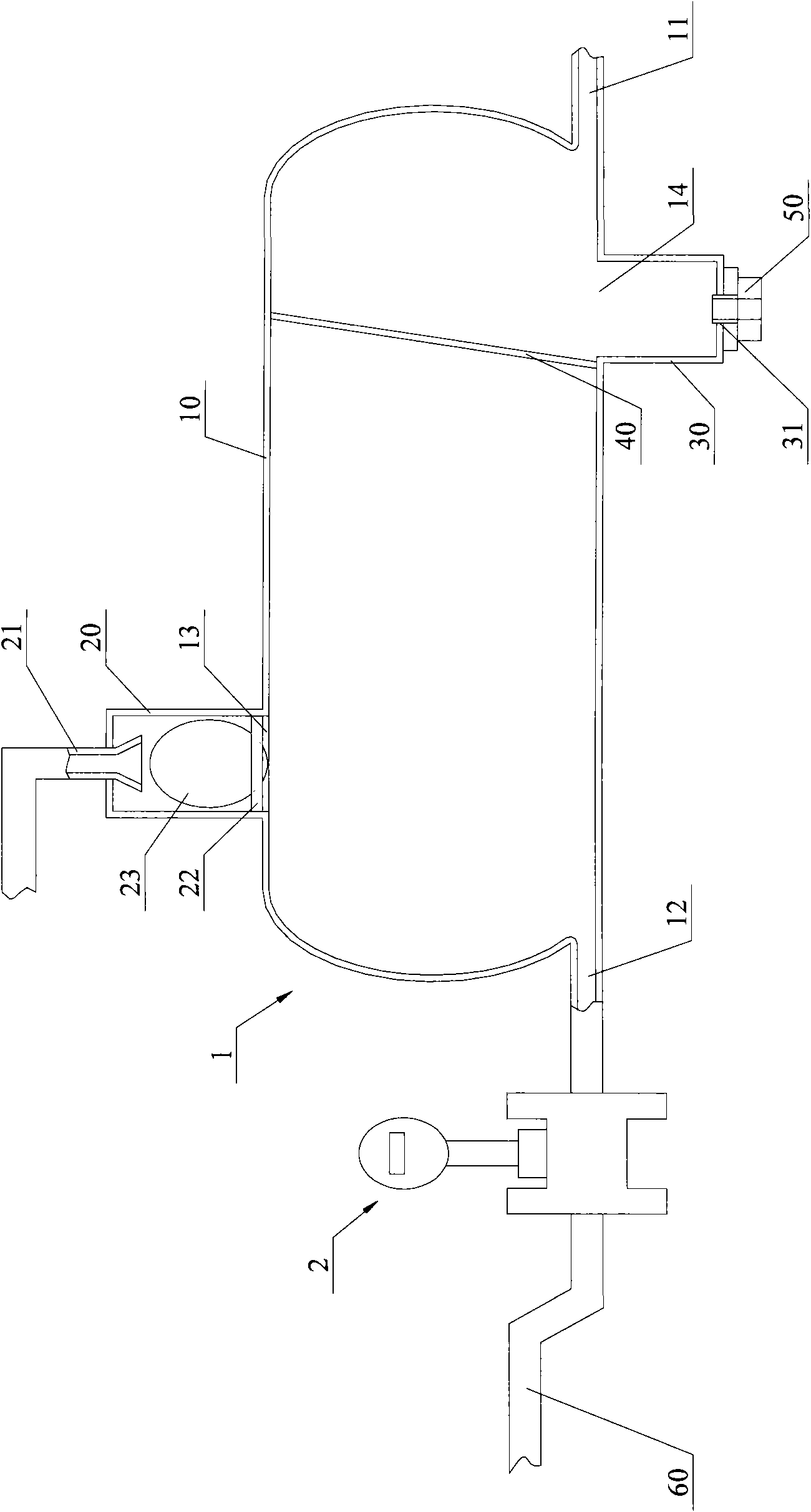
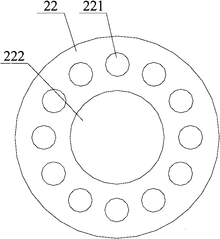
[0026] The core point of the present invention is to provide a separator, which includes a separation tank, a float chamber, an exhaust pipe, a float base and a float ball. Both sides of the separation tank have a liquid inlet and a liquid outlet respectively, and the separator The liquid outlet of the tank is set at the bottom of the separation tank; the float chamber is set at the top of the separation tank and communicates with the separation tank; the exhaust pipe is set at the top of the float chamber and communicates with the The float chamber is connected; the float base is arranged between the separation tank and the float chamber and the separation tank, and there are several ventilation holes on it; the float ball is placed in the float chamber above the float base. When the gas-liquid two-phase fluid enters the separation tank from the liquid inlet of the separation tank, the liquid sinks at the bottom of the separation tank and flows out through the liquid outlet of...


PUM


Abstract

The invention discloses a separator and a flowmeter assembly with the same. The separator provided in the invention comprises a separating tank, a float chamber, an exhaust pipe, a float base and a floating ball, wherein a liquid inlet and a liquid outlet are respectively arranged on both sides of the separating tank, and the liquid outlet of the separating tank is arranged on the bottom of the separating tank; the float chamber is arranged on the top of the separating tank and communicated with the separating tank; the exhaust pipe is arranged on the top of the float chamber and communicatedwith the float chamber; the float base is arranged between the separating tank and the float chamber, and a plurality of vent holes are arranged on the float base; and the floating ball is arranged inthe float chamber above the float base. When the separator is in use, after fluids in gas phase and liquid phase enter the separating tank through the liquid inlet of the separating tank, the liquiddeposits on the bottom of the separating tank and flows out through the liquid outlet of the separating tank, and the gas floats above the liquid and is exhausted through the float chamber and the exhaust pipe on the separating tank, thereby effectively separating the fluids in gas phase and liquid phase. A liquid inlet of the flowmeter of the flowmeter assembly provided by the invention is communicated with the liquid outlet of the separating tank of the separator.

Description

technical field [0001] The invention relates to gas and liquid separation technology, in particular to a separator and a flowmeter assembly with the separator. Background technique [0002] Gas-liquid two-phase flow is a common flow condition in petroleum, chemical, power and other industrial fields, but the flow measurement method of gas-liquid two-phase fluid has always been a difficult problem that has not been well solved. [0003] Especially for the petroleum industry, the two-phase oil well production fluid is accompanied by impurities such as mud and sand. The existing flowmeter cannot be used alone to meet its requirements. It needs to be used in conjunction with separation equipment to obtain high measurement accuracy. [0004] The traditional separation method uses separation equipment to separate the gas-liquid mixture before measurement, which has the advantages of high measurement accuracy, reliable measurement results, and the measurement process is not affecte...

Claims


Application Information

Patent Timeline
IPC IPC(8): B01D36/04B01D19/00G01F15/12
Inventor 蔡长英翟俊民
Owner 北京宝狮油田设备有限公司
Why Eureka
Try Eureka