

Extruder arrangement
A technology of extrusion equipment and extruder, applied in mechanical equipment, gear transmission device, material forming press, etc., can solve the problems of vibration sensitivity and high wear of shift sleeve, and achieve the effect of simple solution
- Summary
- Abstract
- Description
- Claims
- Application Information
AI Technical Summary
Problems solved by technology
Method used
Image

Examples
Embodiment Construction
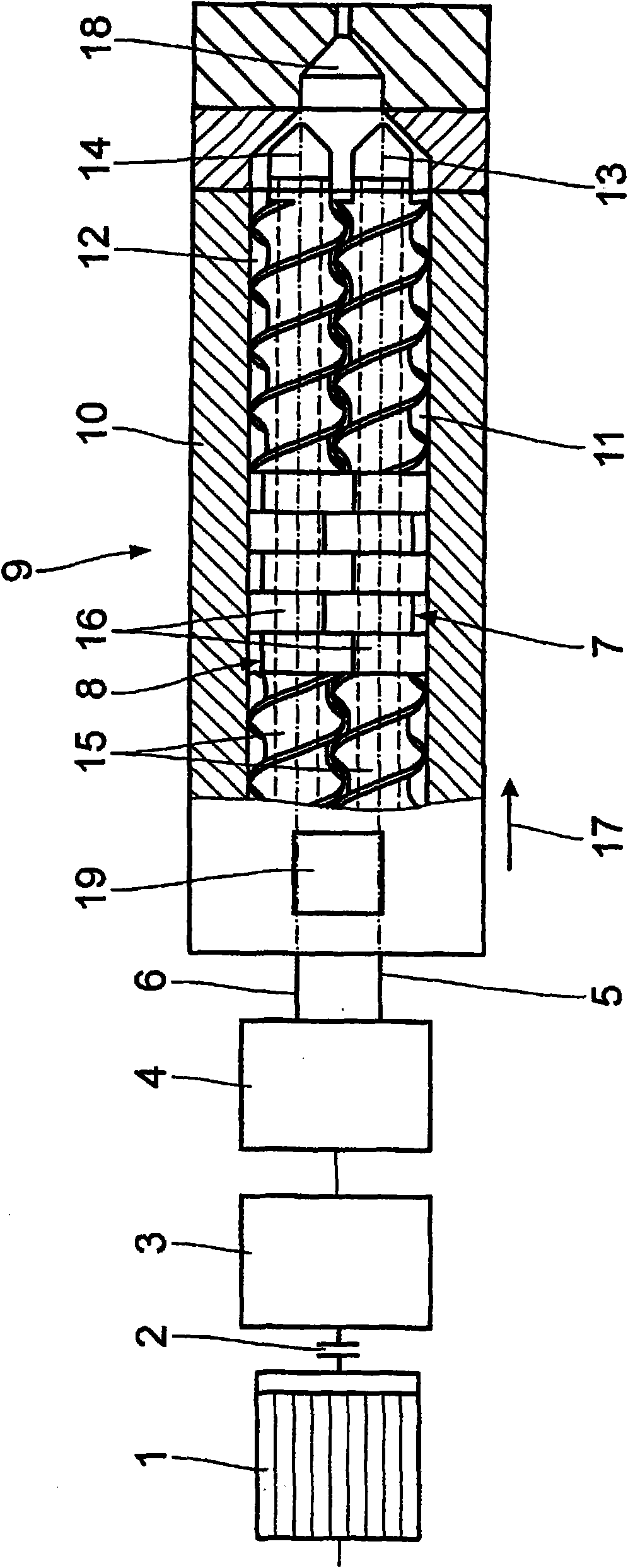
[0016] exist figure 1 The extrusion system shown in has a drive motor 1 which is connected downstream via a clutch / engagement device 2 to a transmission 3 . A conventional transfer case 4 is connected on the speed changer 3, and two co-rotating output shafts 5, 6 are drawn from the transfer case, and the output shafts are connected with the screw shaft / worm screw 7, 8 of an extruder 9 connect. The extruder 9 has a housing 10, in which two 8-shaped staggered holes 11, 12 are arranged, and the holes 11, 12 are connected with the output shafts 5, 6 and the screw shafts 7, 8 in the housing 10. The axes 13, 14 are coaxial. On the screw shafts 7 and 8, a screw part 15 and a molding / mixing part 16 are provided in pairs, respectively. At the downstream end of the housing 10 in the conveying direction 17 of the screw shafts 7 , 8 there is provided a discharge opening 18 for (discharging) the product processed in the extruder 9 in the transfer case. 4 Nearby the material input throu...
PUM
 Abstract
Description
Claims
Application Information