
Novel locomotive traction transmission device

A technology for traction transmission and locomotives, applied in the direction of power units, electric power units, vehicle components, etc., can solve the problems of uneven impact load, increase the wall thickness of armature hollow shaft, and corrugated wear of rails, etc., and achieve simplified processing and assembly Effect

Inactive Publication Date: 2010-03-31
DALIAN JIAOTONG UNIVERSITY
View PDF0 Cites 9 Cited by
  • Summary
  • Abstract
  • Description
  • Claims
  • Application Information

AI Technical Summary

Problems solved by technology

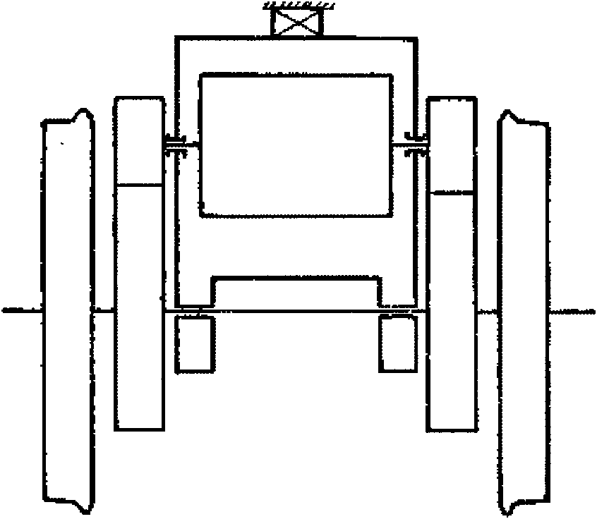
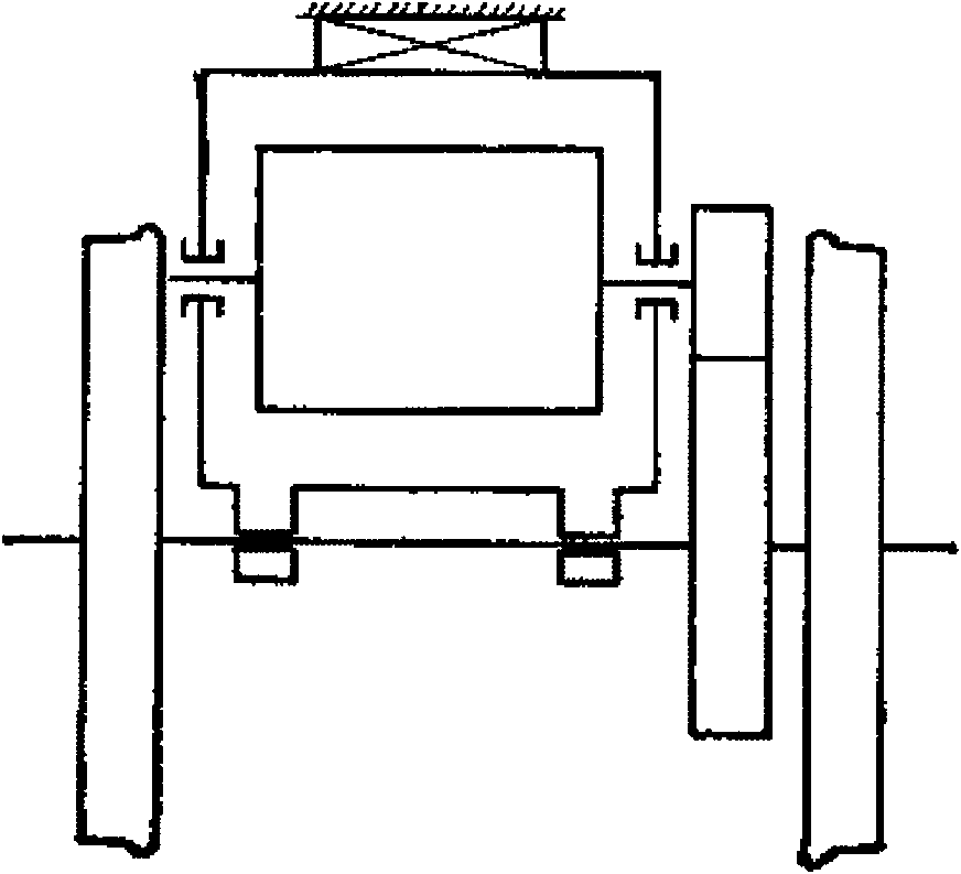
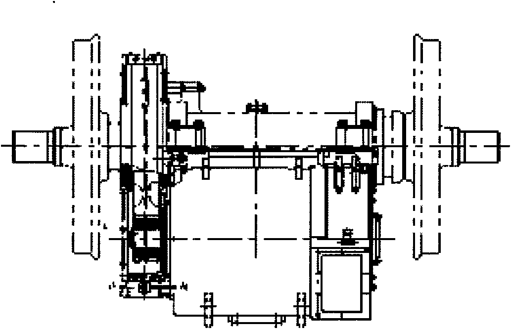
[0007] Through the above-mentioned analysis of the mechanism of the rigid shaft suspension traction transmission device and the proof in the locomotive operation practice, it has the following problems: 1. The unsprung mass is large, which has a relatively high dynamic effect on the superstructure of the line; 2. The opposite wheel The transmission torque is not uniform, which will lead to increased wear of the wheel tire, corrugated wear of the rail, and the performance of the locomotive adhesion may be greatly reduced; 3. The bearing bush (or image 3 The holding bearing in the center) absorbs all the impacts and collisions when the wheelset passes through the turnout, rail joint and other uneven lines, so that the displacement between the wheelset and the bogie frame can reach 30-40mm, then the traction motor under this condition The vibration acceleration is as high as 25g, which is a huge damage to both the bearing and the rolling bearing in the motor.
[0048] The impact load on the motor bearing in unilateral transmission is uneven. Although the axial space is larger than that of bilateral transmission, the motor volume can be designed slightly larger, which is beneficial to increase the power of the motor, but the torque and deformation of the hollow shaft are both bilateral. Twice that of the transmission, and the wall thickness of the hollow shaft of the armature is required to be increased

Method used


Image

  • Novel locomotive traction transmission device
  • Novel locomotive traction transmission device
  • Novel locomotive traction transmission device

Examples


Embodiment Construction

[0098] Now in conjunction with accompanying drawing, the present invention is described in further detail:

[0099] Such as Figure 20 As shown, it has the advantages of both bearing type and frame type. When the road condition is good and the locomotive runs at high speed, the vertical impact of the line on the wheel set is small, but the vibration frequency is relatively high. Therefore, frame type should be used. However, when the road conditions are poor and the locomotive must be slowed down, the vertical impact on the wheel set is severe, but the vibration frequency is low, so in this case, the bearing-type traction transmission scheme should be adopted.

[0100] To achieve the above scheme, if Figure 21 The new locomotive traction drive shown includes bogie frame 4, bearing 6, traction motor 7 (including motor stator 7(a), hollow shaft 7(b), motor rotor 7(c)), wheel set 10, locomotive The moving shaft 5 and the traction motor 7 are located between the wheel set 10 an...


PUM


Abstract

The invention relates to a novel locomotive traction transmission device, which comprises a bogie frame, a traction motor, a wheel set, a locomotive driving shaft and a traction motor hollow shaft, wherein the motor is positioned between middle beams and end beams of the wheel set and the bogie frame. The device is characterized in that the device also comprises an elastic coupling, elastic motorsuspension and elastic elements symmetrically arranged on the inner walls of two ends of the traction motor hollow shaft, and the stiffness of the elastic coupling, the elastic motor suspension and the elastic elements on the inner walls of two ends of the traction motor hollow shaft is different and successively increases. The device absorbs the advantages of a bearing type and a frame-supportingtype. When road conditions are good, a locomotive runs at a high speed, and then the vertical impact displacement of a line on the wheel set is low but vibration frequency is high, thus the working mode of the device is the same with the structure of a frame-supporting type wheel set hollow shaft. When road conditions are bad, the locomotive needs to slow down to run, and then the vertical impactdisplacement on the wheel set is intense but the vibration frequency is low, thus the working mode of the device is the same with that of a bearing-type traction transmission structure.

Description

technical field [0001] The invention relates to a novel locomotive traction transmission device. Background technique [0002] The traction transmission device of a railway locomotive is a mechanical device that transmits the rotational torque generated by the traction motor to the wheel set. In the drive device of a traditional locomotive, a gear transmission is used to drive the high-speed, small-torque traction motor to drive the one with a large resistance torque. The locomotive drive shaft is a deceleration device. The most basic requirement of this device is: when the locomotive runs on an uneven track or passes through a switch, there will be relative motion in all directions between the wheelset of the unsprung part and the frame of the sprung part. At this time, it is required that the traction transmission device can stably transmit the motor torque to the locomotive driving wheel under the change of this displacement. [0003] As the speed of locomotives increas...

Claims


Application Information

Patent Timeline
IPC IPC(8): B61F5/00B60K1/00
Inventor 葛研军杨均悦刘长颖张文跃吴艳波
Owner DALIAN JIAOTONG UNIVERSITY
Learn More