

Drum-type heavy sheet abrasion monitoring sensor, alarming system and drum-type heavy sheet abrasion monitoring method
A technology for monitoring alarms and sensors, applied in the field of auto parts, can solve problems such as hidden safety hazards, real-time wear and tear, and the wear and tear to the limit state should not be found, brake failure, etc., to achieve the effect of reducing waste, simple structure, and not easy to wear
- Summary
- Abstract
- Description
- Claims
- Application Information
AI Technical Summary
Problems solved by technology
Method used
Image

Examples
Embodiment 1
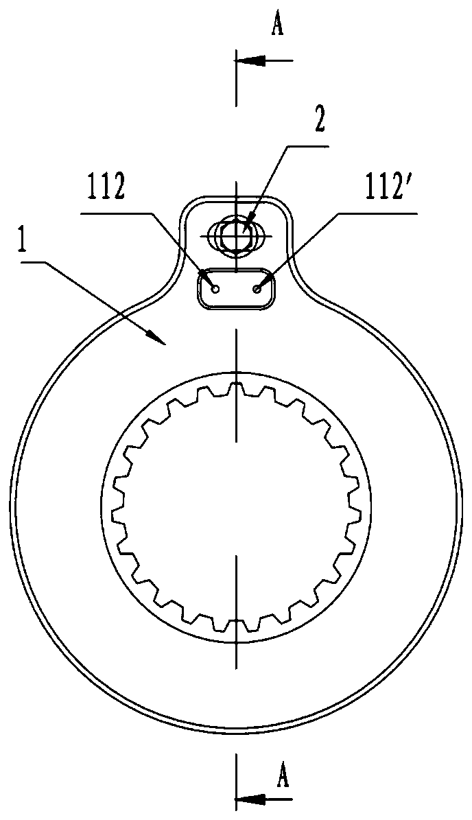
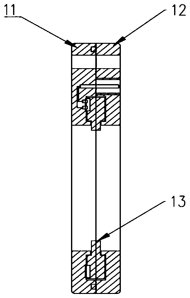
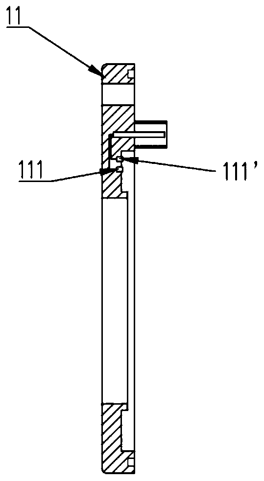
[0045] This embodiment discloses a drum-type heavy-duty sheet wear monitoring sensor, such as figure 1 As shown, it includes an inner shell 11, an outer shell 12 and a rotating disk 13; the inner shell 11 and the outer shell 12 are snap-fit structures, but are not limited to snap-fit, and can also be screwed or bolted; the inner shell 11 and the outer shell 12 have a A cavity for placing the rotating disk, for placing the rotating disk; the inner shell 11 is equipped with two metal contacts 111, 111' and two terminal posts 112, 112', the metal contacts are connected to the terminal posts, and the terminal posts are connected to the counting sensor 3. The rotating disk 13 in the wear sensor 1 is fixedly connected to the camshaft 5. In this embodiment, the rotating disk 13 is meshed with the camshaft 5 through gears. In other embodiments, other fixed connection methods can also be used; and for To achieve meshing connection, the inner shell 11, the outer shell 12 and the cente...
Embodiment 2
[0051] This embodiment discloses a drum-type heavy sheet wear monitoring and alarm system, such as Figure 8 As shown, it includes the wear sensor 1 and the alarm device 4 described in Embodiment 1; wherein the count sensor 3 is connected to the alarm device 4; preferably, the count sensor 3 is also provided with a count display device.
[0052] Calculate and set the counting peak value K according to the limit rotation angle of the S camshaft 5;
[0053] Counting peak K=S camshaft limit rotation β angle / S camshaft single rotation α angle.
[0054] Such as Figure 5 As shown, adding one to the number on the counting sensor means that the S camshaft 5 rotates α angle, where α=360 / n; n represents the number of teeth of the metal sheet, and the larger n represents the smaller the S camshaft 5 rotates α angle, which means The more accurate the wear sensor 1 is; the number of teeth on the metal ring is preferably 100-150; in this embodiment, it is more preferably 125 teeth, and t...
Embodiment 3
[0058] This embodiment discloses a method for monitoring wear of a drum-type heavy-duty sheet, wherein this embodiment uses the wear sensor and its alarm system described in Embodiment 1 and Embodiment 2; the steps include:
[0059] (1) Obtain the limit angle β according to the limit value of the camshaft rotation angle;
[0060] (2) set the number n of metal ring sheet teeth on the wear sensor; calculate the angle α=360 ° / n between adjacent teeth;
[0061] (3) Calculate the counting peak value K, whose calculation formula is: K=β / α;
[0062] (4) Preset counting alarm value K', where K'≤K;
[0063] (5) When the counting value of the counting sensor reaches the preset value K', the counting sensor transmits the signal to the alarm device, and an alarm is given.
[0064] Preferably, the K' value can be set to a number of values less than or equal to K, and when the preset value K' is reached, a digital alarm will be issued, which will help the driver to monitor the wear of t...
PUM
 Abstract
Description
Claims
Application Information