Bottle lifting method and bottle lifting mechanism for bottle unscrambler

A technology of a bottle unscrambler and a chain transmission mechanism, applied in the field of bottle unscramblers, can solve the problems of glass bottles lacking three-dimensional force bearing support, destroying the acid-base concentration of the bottle washing process, wasting resources, etc., and achieving a simple and ingenious structure and stable bottle lifting. Reliable, energy-saving effect

Inactive Publication Date: 2013-08-21
杨晖伟
View PDF1 Cites 0 Cited by
  • Summary
  • Abstract
  • Description
  • Claims
  • Application Information

AI Technical Summary

Problems solved by technology

And this background technology also has following defect: the one, glass bottle lacks the carrying support of three-dimensional three-dimensional force, so, easily topple over when lifting bottle
The second is that it needs and consumes more energy. Using the power of the air compressor, with the help of the role of the cylinder, the devices on the lifting bottle feeding table are lifted, squeezed, blocked, and pushed, and the energy consumption is relatively large.
The third is that there is no process of pouring water. A certain amount of water is filled in the straightened bottle, and the bottle unscrambler of this background technology will bring the water in the bottle into the production line, and the water in the bottle will enter the follow-up process such as washing the bottle together with the bottle. During the process, the acid-base concentration of the bottle washing process will be destroyed, which will be unfavorable to the follow-up work. Moreover, the circulating water tank of the bottle unscrambler needs to replenish a large amount of water continuously. The result of this method is that the circulating water is only partial and wastes resources.

Method used


Image

  • Bottle lifting method and bottle lifting mechanism for bottle unscrambler
  • Bottle lifting method and bottle lifting mechanism for bottle unscrambler
  • Bottle lifting method and bottle lifting mechanism for bottle unscrambler

Examples


Embodiment Construction

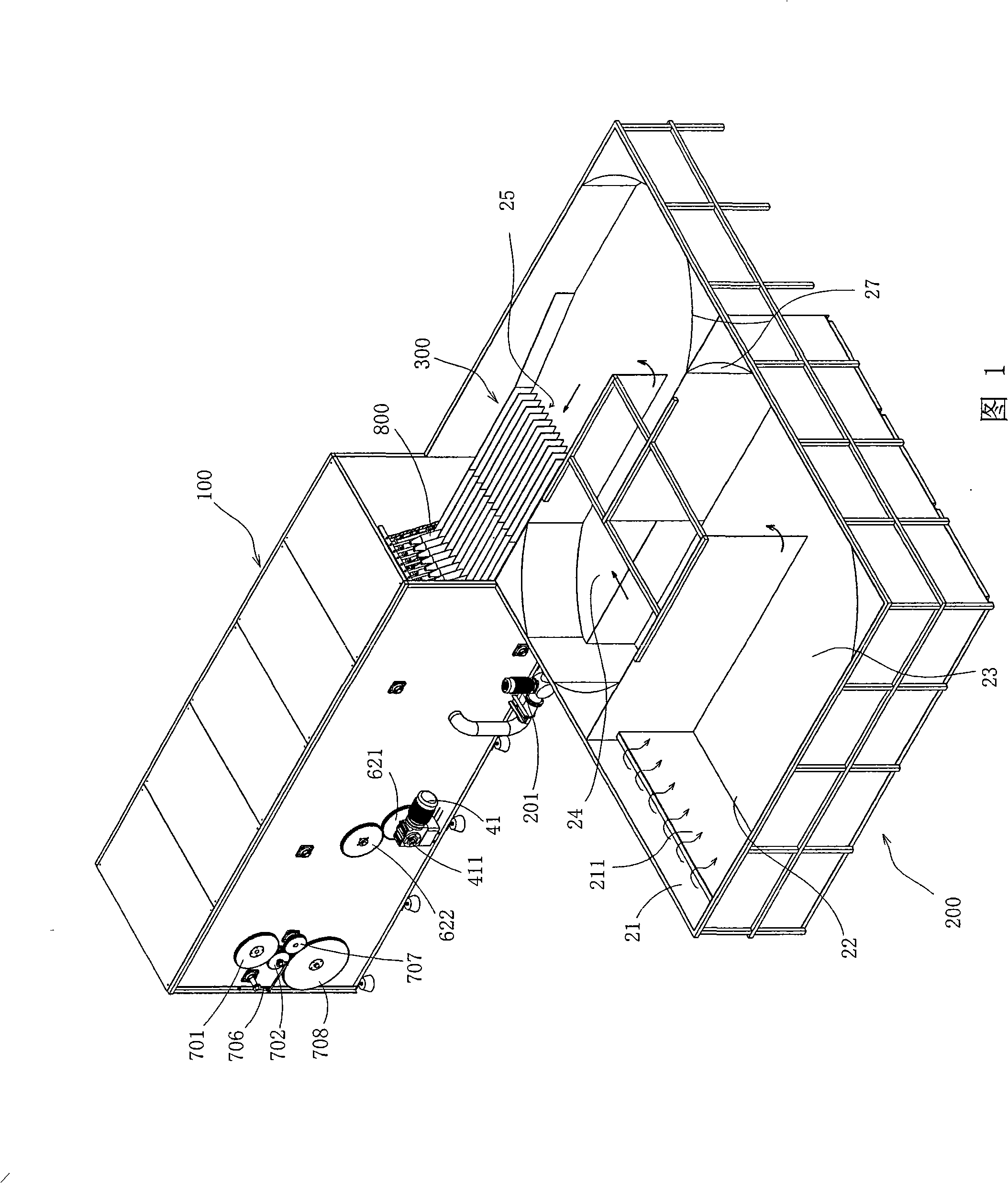
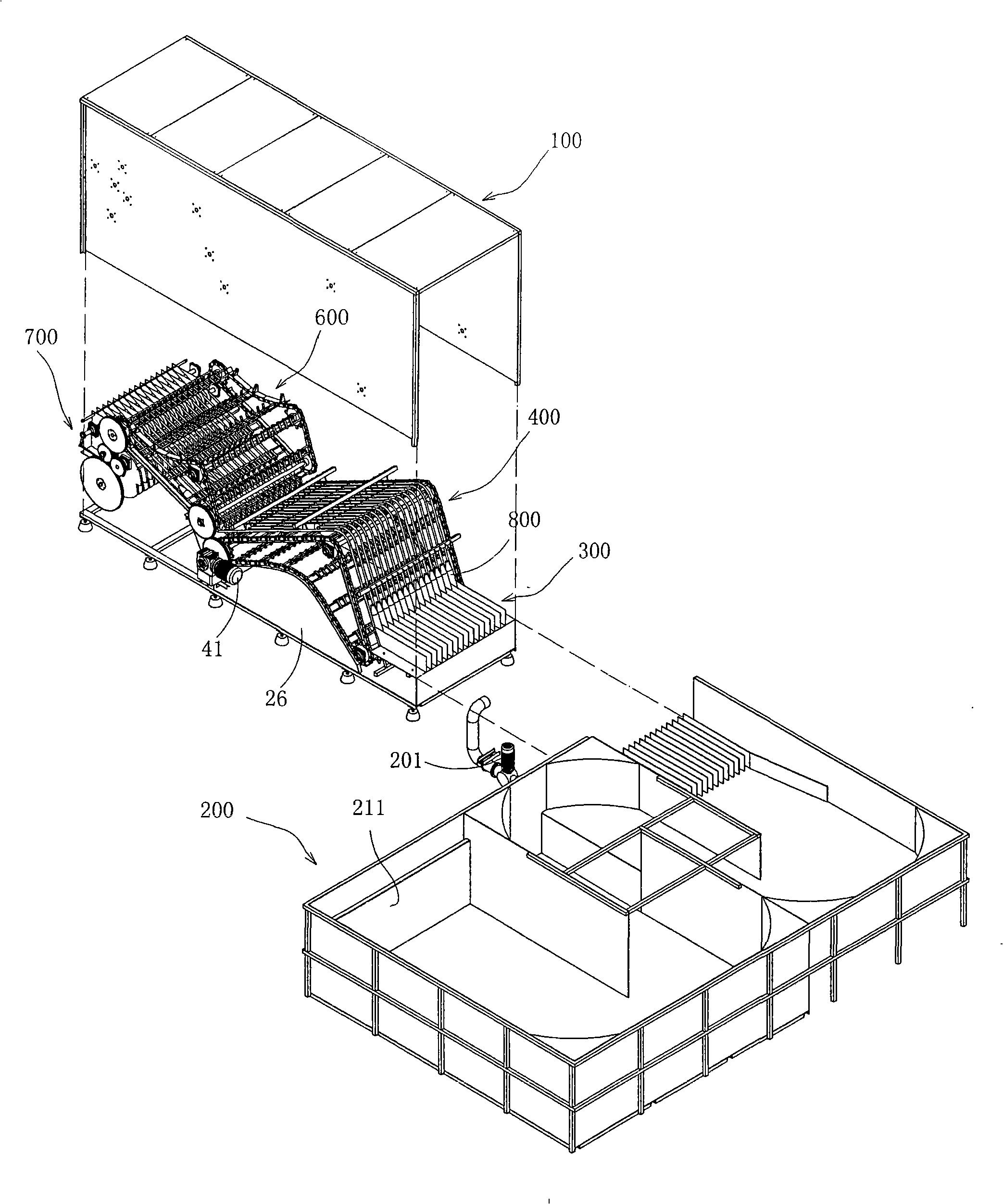
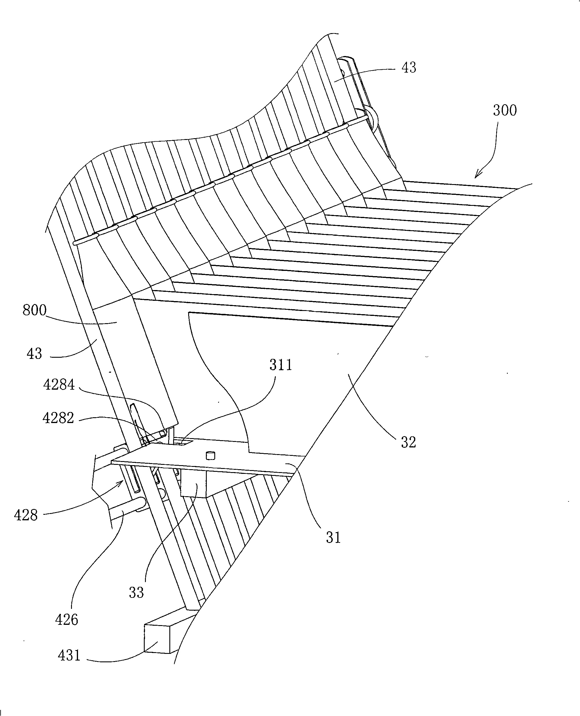
[0033] Such as figure 1 , 2 , 5, the bottle unscrambler of the present invention comprises a housing 100, a control box (not shown in the figure) of a control motor 41 and a pump 201, a liquid pool 200, and a pump that transports liquid to form a circulating fluid flow in the liquid pool 201 and the conveying pipe, the tail end of the liquid pool is connected with the shell, and a lane-dividing mechanism 300 is provided at the joint. The outer end of the lane-dividing mechanism is a bottle lifting mechanism 400, a liquid pouring mechanism, a bottle turning mechanism 600, and a bottle dropping mechanism 700. , wherein, the housing 100 is formed by a steel plate and a bracket structure, and the bottom end is provided with feet placed on the ground; the liquid in the liquid pool can be water, and the depth can be more than twice the height of the bottle. Preparation, the liquid can also be lye or acidic liquid to soak the bottle.

[0034] Such as figure 1 , figure 2 , the li...


PUM


Abstract

A bottle lifting method for a bottle unscrambler comprises the following steps: at the tail end of a liquid cell (200), letting glass bottles (800) to be unscrambled to float in the liquid vertically in a way that bottoms thereof face downwards; lifting a glass bottle upwards from the bottom thereof with first bottle hooks to upwards move the glass bottle out of the liquid cell. A bottle lifting mechanism (400) using the bottle lifting method is positioned outside the tail end of the liquid cell, and comprises a motor (41), a transmission mechanism driven by the motor, and the first bottle hooks (427, 428) driven by the transmission mechanism to lift the glass bottle upwards from the bottom thereof. The bottle lifting method and the bottle lifting mechanism can lift bottles reliably and orderly while the glass bottles are not easy to damage. When a slide rail for carrying the glass bottle is further utilized to match the first bottle hooks to lift the bottles, the bottles can be lifted stably and easily; and the structure is simple and is easy to connect the next working procedure of pouring out the liquid in the bottles. The bottle lifting method and the bottle lifting mechanism have proper functions, low cost and high efficiency.

Description

[0001] This application is a divisional application. The filing date of the original application is: May 8, 2008. The application number of the original application is: 200810067101.5. technical field [0002] The present invention relates to a bottle unscrambling method and a bottle unscrambling machine using the method, in particular to a bottle unscrambling method and a bottle unscrambling machine which use liquid flow to make open glass bottles automatically float upright and then unscramble the bottles. The bottle opening method and the bottle opening mechanism. Background technique [0003] The bottle unscrambling mode of existing beer glass bottle is generally manual bottle unscrambling, and labor intensity is high, and cost is high, and breakage rate is high, and efficiency is low. The Chinese patent application published on March 28, 2007 with the publication number CN 1935624A discloses a "buoyancy vertical bottle unscrambler", which is connected to the front of th...

Claims


Application Information

Patent Timeline
Patent Type & Authority Patents(China)
IPC IPC(8): B65G17/06B65G17/30B65G47/22B65G51/01
Inventor 杨晖伟
Owner 杨晖伟
Why Eureka
Try Eureka