
Method of optimizing interference coefficient of coherence on the basis of polarimetric synthetic aperture radar (SAR)

A technology of interferometric synthetic aperture and coherence coefficient, which is used in the re-radiation of electromagnetic waves, radio wave measurement systems, reflection/re-radiation of radio waves, etc., and can solve problems such as limited improvement of interference coherence.

Inactive Publication Date: 2010-03-31
INST OF ELECTRONICS CHINESE ACAD OF SCI
View PDF0 Cites 21 Cited by
  • Summary
  • Abstract
  • Description
  • Claims
  • Application Information

AI Technical Summary

Problems solved by technology

In addition, Lu Bai tried to use the eigendecomposition result as the initial estimate, and whether the interference coherence can be improved as the result convergence condition, but this method still requires the matrix (T 11 +T 22 ) reversible[8]
Tao Xiong compared the interference results of the three polarization states of HH, HV, and VV as the optimal result of the interference phase with the greatest interference coherence [9]. Although the algorithm has high computational efficiency, the degree of improvement in the interference coherence is limited

Method used

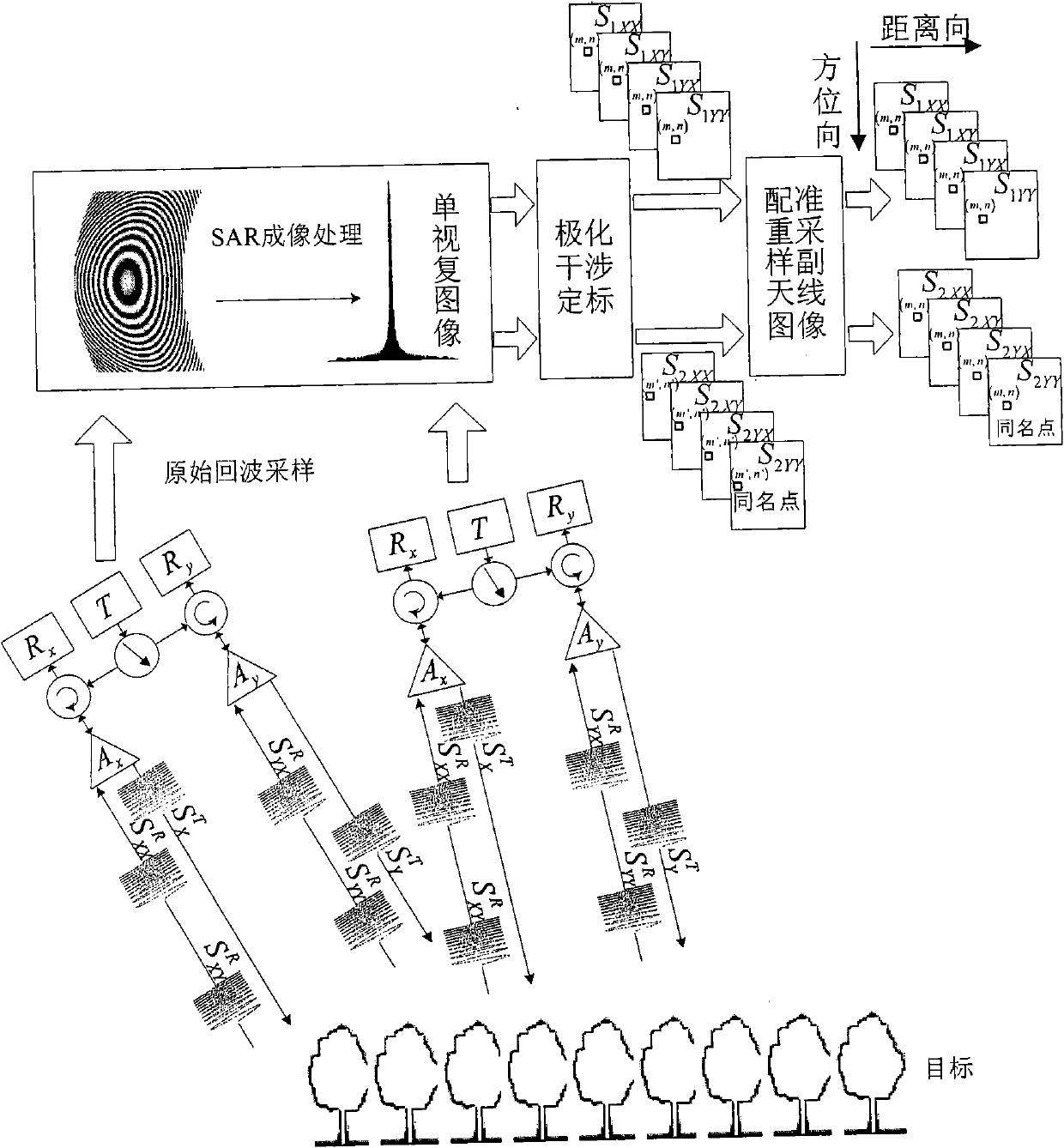

Image

  • Method of optimizing interference coefficient of coherence on the basis of polarimetric synthetic aperture radar (SAR)
  • Method of optimizing interference coefficient of coherence on the basis of polarimetric synthetic aperture radar (SAR)
  • Method of optimizing interference coefficient of coherence on the basis of polarimetric synthetic aperture radar (SAR)

Examples


Embodiment Construction

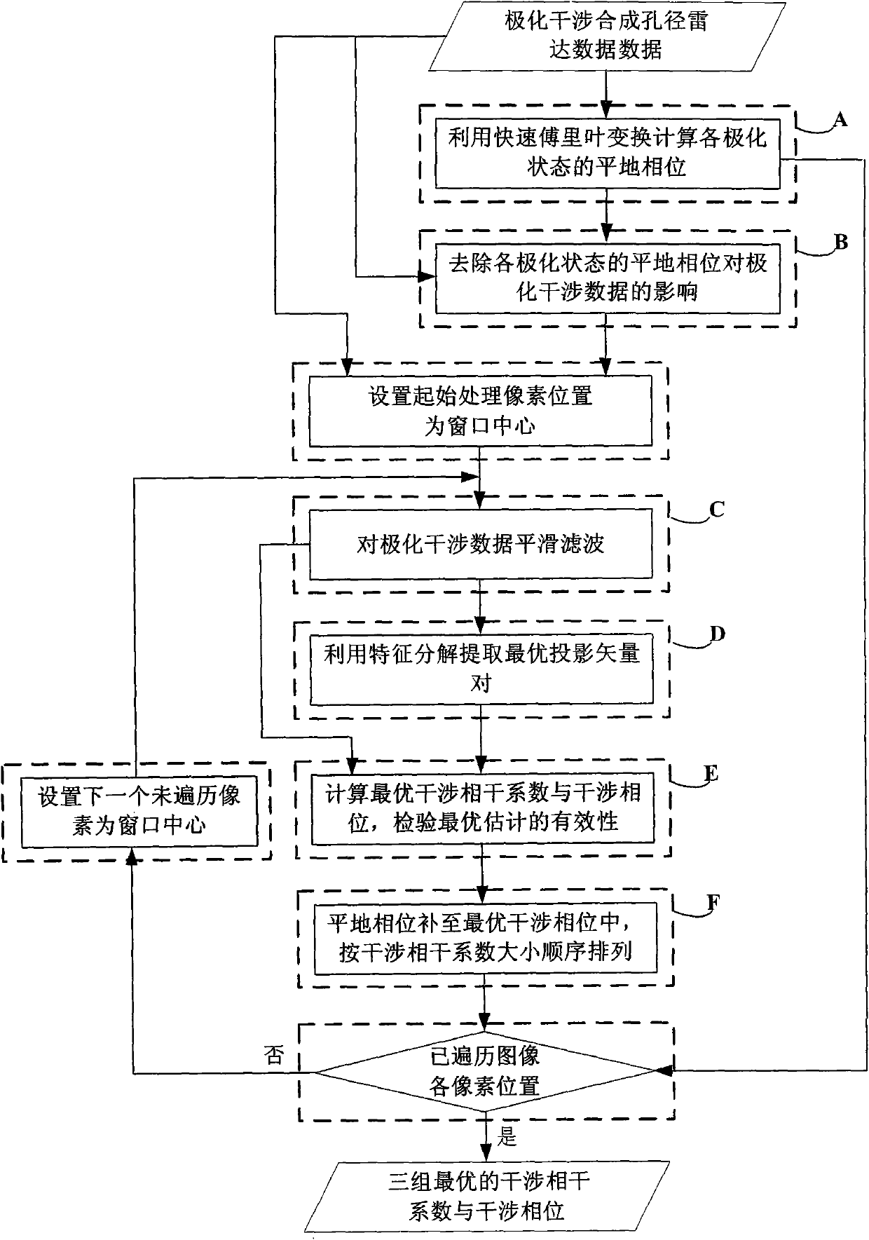
[0124] Such as figure 2 As shown, the method for optimizing the interferometric coherence coefficient based on polarization interferometric SAR data includes the following steps:

[0125] A) Calculate the flat-earth phase of each polarization state by fast Fourier transform;

[0126] B) Remove the influence of the flat-earth phase of each polarization state on the polarization interference data;

[0127] C) smoothing and filtering the polarization interference data;

[0128] D) Utilize eigendecomposition to extract the optimal projection vector pair;

[0129] E) Calculate the optimal interferometric coherence coefficient and interferometric phase, and check the validity of the optimal estimate;

[0130] F) Compensate the flat earth phase to the optimal interferometric phase, and arrange the optimal interferometric coherence coefficient and the optimal interferometric phase in order of the magnitude of the interferometric coherence coefficient.

[0131] Step A) Calculating...


PUM


Abstract

The present invention provides a method of optimizing interference coefficients of coherence on the basis of polarimetric synthetic aperture radar (SAR) data, relating to the SAR technology. The method comprises steps of firstly calculating the flattening phase of each polarized state by utilizing a fast fourier transformation (FFT) method; eliminating an influence of the flattening phase of eachpolarized state on polarimetric data; performing smooth filtering to the polarimetric data; extracting the optimal projection vector pair by using an eigen-decomposition method; calculating the optimal interference coefficient of coherence and the optimal interference phase and verifying the validity of the optimal estimation; compensating the optimal interference phase by the flattening phase, and arranging the optimal interferences coefficient of coherence and the optimal interference phases in a value sequence of the interference coefficients of coherence. The method of the present invention is not limited by a condition that a polarimetric data matrix is invertible, dispenses with the compensation of absolute offset between the optimal projection vectors and can verify the validity ofthe optimal result. The method of the invention has characteristics of a simple principle and convenience in calculation and can be applied in processing of data of polarimetric classification, parameter inversion and the like.

Description

technical field [0001] The invention relates to the technical field of synthetic aperture radar remote sensing information processing, and is a method for optimizing the interference coherence coefficient based on single baseline polarization interference synthetic aperture radar data, which can simply and quickly realize the optimization of the interference coherence coefficient and extract the corresponding scattering center the interference phase. Background technique [0002] The polarimetric interferometric synthetic aperture radar technology introduces full polarization data into the interferometric processing, which not only makes use of the sensitivity of the polarization information to parameters such as the shape, direction, and dielectric coefficient of the scatterer[1], but also obtains height, Motion and deformation information, so it has more prominent advantages than the single interference or polarization SAR in information extraction, classification and othe...

Claims


Application Information

Patent Timeline
IPC IPC(8): G01S7/41G01S7/48G01S13/90G01S17/89
Inventor 白璐洪文曹芳
Owner INST OF ELECTRONICS CHINESE ACAD OF SCI
Learn More