Supercharge Your Innovation With Domain-Expert AI Agents!

Display unit, display unit driving method and display system

A technology of display unit and display system, applied in static indicators, cathode ray tube indicators, instruments, etc., can solve problems such as high or particularly low, excessive leakage current of switch 16, switch damage, etc.

Active Publication Date: 2010-03-31
IND TECH RES INST
View PDF0 Cites 0 Cited by
  • Summary
  • Abstract
  • Description
  • Claims
  • Application Information

AI Technical Summary

Problems solved by technology

[0003] Depend on figure 1 learned that the switch 14 outputs the drain control signal V Dn To the capacitor 16 and one end of the pixel 14, due to the capacitive coupling effect, before the switch 14 is turned on, the alternating V com signal will cause the drain control signal V Dn The voltage will be extremely high or extremely low, causing the switch 16 to generate excessive leakage current or causing damage to the switch

Method used


Image

  • Display unit, display unit driving method and display system
  • Display unit, display unit driving method and display system
  • Display unit, display unit driving method and display system

Examples


Embodiment Construction

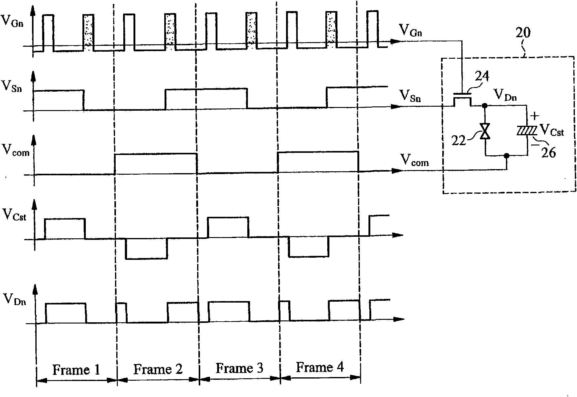
[0014] figure 2 is to display the display unit 20 according to the first embodiment of the present invention and a plurality of signals V Gn , V Sn , V com , V Cst and V Dn timing diagram. The display unit 20 includes a switch 24, a pixel 22 and a capacitor 26. The switch 24 may be composed of a transistor, and the switch 24 includes a first terminal receiving a source control signal V Sn , the second terminal receives the switch control signal V Gn and the third end are coupled to the pixel 22 and the capacitor 26, wherein the switch 24 is controlled according to the switch control signal V Gn turn-on enables the source control signal V Sn It is transmitted to the pixel 22 and the capacitor 26 through the third terminal. When the switch 24 is turned on, the source control signal V Sn and the drain control signal V Dn is the same potential. The capacitor 26 has two terminals respectively receiving the drain control signal V Dn and common voltage signal V com , and...


PUM


Abstract

The invention relates to a display unit which comprises a capacitor, pixels and a switch, wherein two terminals of the capacitor respectively receive drain control signals and common voltage signals,and the capacitor charges or discharges according to the voltage difference between the drain control signals and the common voltage signals; two terminal points of each pixel respectively receive thedrain control signals and the common voltage signals, and the pixels display images according to the voltage difference between the drain control signals and the common voltage signals; the switch comprises a first terminal for receiving source control signals, a second terminal for receiving switch control signals, and a third terminal coupled with the pixel and the capacitor; the switch is conducted according to the switch control signals to transmit the source control signals to the pixel and the capacitor through the third terminal; and the switch is conducted twice in one frame accordingto the switch control signals, first conduction enables the pixel to display images, and second conduction enables the capacitor to discharge to prevent the voltage level of the third terminal from exceeding a predetermined voltage.

Description

technical field [0001] The present invention relates to a display driving method, in particular to a method for AC-V com display driver circuit. Background technique [0002] figure 1 is to display a conventional display unit 10 and multiple signals V Gn , V Sn , V com , V Cst and V Dn timing diagram. The display unit 10 includes a switch 14, a pixel 12 and a capacitor 16, the switch control signal V Gn The control switch 14 is turned on or off. When the switch 14 is turned on, the source control signal Vsn and the drain control signal V Dn is the same potential, and the capacitor 16 is based on the drain control signal V Dn and common voltage signal V com The voltage difference is charged, the pixel 12 and the capacitor 16 are coupled in parallel, one end of which receives the drain control signal V Dn , the other end receives the common voltage signal V com , if there is a voltage difference between the two ends of the pixel 12, the pixel 12 will display images...

Claims


Application Information

Patent Timeline
IPC IPC(8): G09G5/00
Inventor 陈奕呈陈恒殷梁兆钧
Owner IND TECH RES INST
Features
  • R&D
  • Intellectual Property
  • Life Sciences
  • Materials
  • Tech Scout
  • Unparalleled Data Quality
  • Higher Quality Content
  • 60% Fewer Hallucinations
Learn More