Rotary index device in machine tool

A technology for working machines and indexing devices, which is applied to metal processing machinery parts, mechanical equipment, manufacturing tools, etc., can solve problems such as the reduction of machining accuracy, and achieve the effect of preventing the reduction of machining accuracy.

Inactive Publication Date: 2010-03-31
TSUDAKOMA KOGYO KK
View PDF2 Cites 4 Cited by
  • Summary
  • Abstract
  • Description
  • Claims
  • Application Information

AI Technical Summary

Problems solved by technology

In addition, if the case is deflected, the rotating shaft supported by the case via bearings or the like will be tilted and the machining accuracy will be reduced.

Method used


Image

  • Rotary index device in machine tool
  • Rotary index device in machine tool
  • Rotary index device in machine tool

Examples


Embodiment Construction

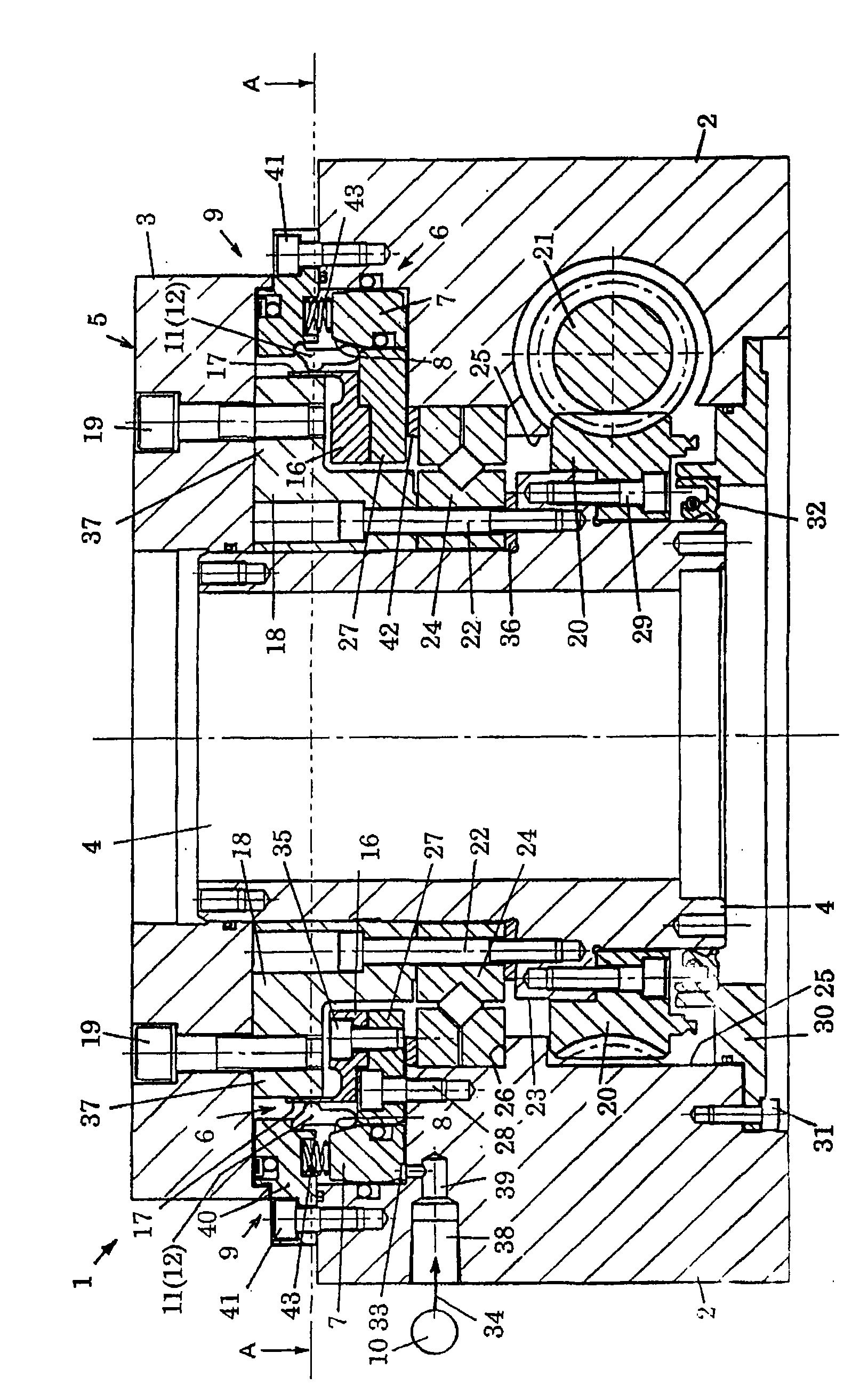
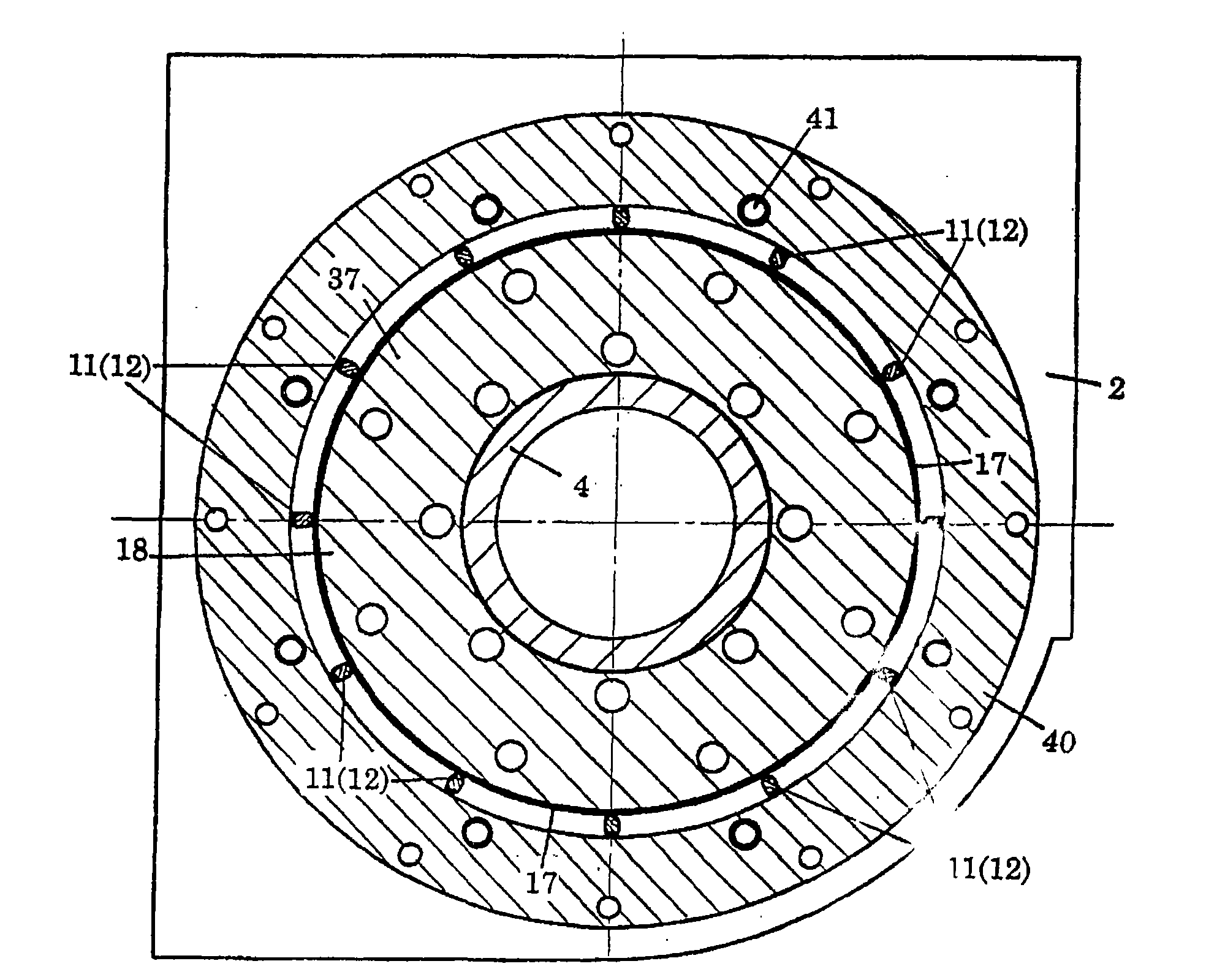
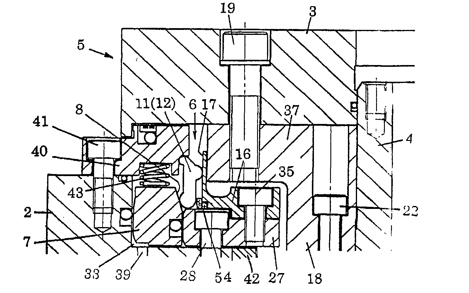
[0062] 1 to 4 show typical examples of applying the rotary indexing device 1 for machine tools according to the present invention to a rotary table device. In these Figures 1 to 4, the rotary indexing device 1 of a working machine includes: a rotary shaft 4 freely rotatably provided in a casing 2, a rotary body 5 including this rotary shaft 4, and a The clamping device 6 acts on the body 5 in the radial direction of the rotating shaft 4 and maintains the indexed rotational angle position of the rotating body 5 .

[0063] The rotating shaft 4 is, for example, a hollow body rotatably provided inside the receiving hole 25 of the casing 2, and the circular table 3 as a member to be driven to rotate is attached relatively non-rotatably to the end thereof. This round table 3 is arranged parallel to one surface of the block-shaped casing 2, and is fitted to the rotating shaft 4 at the central hole portion, and is fixed to a part of the rotating body 5 by a plurality of mounting bolts...


PUM


Abstract

A rotary index device in which the rotating shaft is held surely and stably after indexing. In the rotary index device of a machine tool comprising a rotating shaft provided rotatably in the housing and having an end portion to which a circular table is secured, and a clamp device for holding the rotational angular position of a body of revolution after indexing by making a pressing force act in the radial direction of the rotating shaft to the body of revolution including the rotating shaft, the clamp device includes a piston member provided displaceably in the axial direction of the rotatingshaft within the housing and having a tapered face formed on the side face, a means interposed between the body of revolution and the piston member, receiving a pressing force in the axial directionof rotation of the rotating shaft from the piston member as it displaces and making the pressing force act on the body of revolution while converting into the radial direction of the rotating shaft, and a means for urging the piston member in the direction for generating the pressing force from the pressing force conversion means.

Description

technical field [0001] The present invention relates to a device for rotating a round table and indexing a workpiece on the round table to a predetermined rotation angle in a working machine. Background technique [0002] Patent Document 1 discloses a disk-type clamping device, and Patent Document 2 discloses a sleeve-type clamping device. [0003] In general, a disc-type clamping device has a clamping disc that is fixed in a pattern extending in its radial direction with respect to the rotating shaft, by connecting the outer peripheral end of the clamping disc through the clamping surface of the housing and The piston member and the like are clamped (clamped) to maintain an indexed angular position of the rotating shaft. [0004] In such a disk-type clamping device, the angular position is maintained by clamping the outer peripheral end of the thin-plate-shaped clamping disk. When the workpiece is processed, loads are applied to the rotation axis and the rotation direction...

Claims


Application Information

Patent Timeline
Patent Type & Authority Applications(China)
IPC IPC(8): B23Q16/10B23Q1/28
CPCB23Q16/107B23Q16/102Y10T74/1494
Inventor 辰田好教
Owner TSUDAKOMA KOGYO KK
Why Eureka
Try Eureka