Polarization conversion system and method for stereoscopic projection
A polarization conversion and polarization technology, applied in the field of polarization conversion systems, can solve problems such as reducing brightness, unsatisfactory viewing experience, and limitations
- Summary
- Abstract
- Description
- Claims
- Application Information
AI Technical Summary
Problems solved by technology
Method used
Image
Examples
no. 1 approach
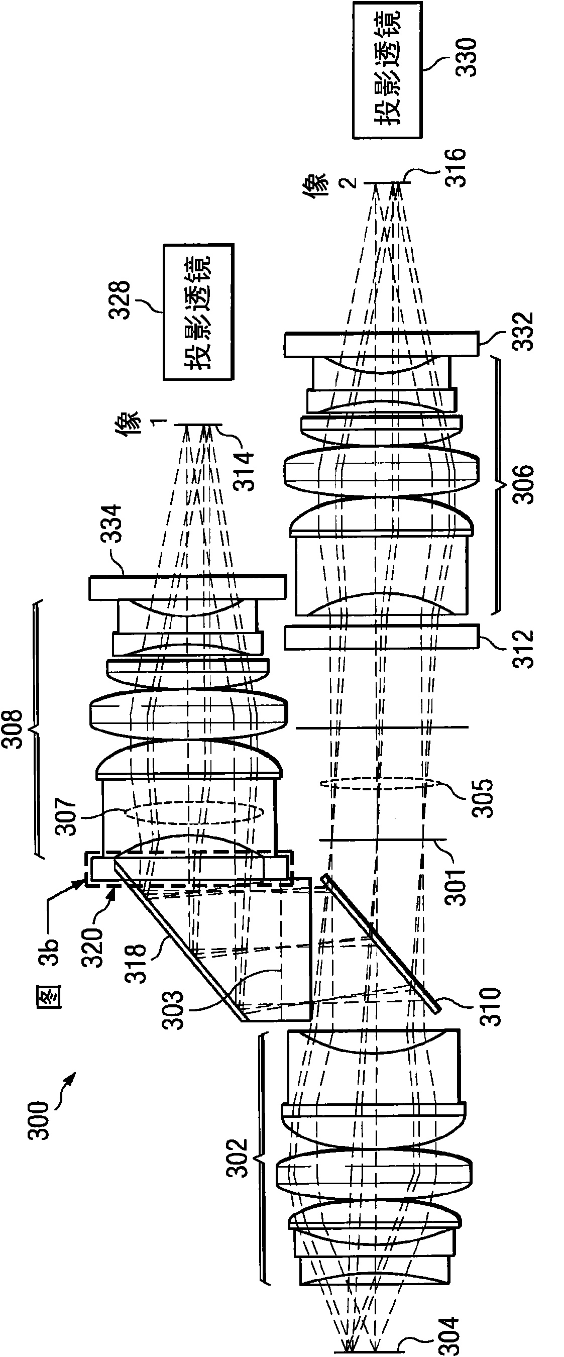
[0026] image 3 is a schematic diagram illustrating a first embodiment of a polarization conversion system (PCS) 300 . In general, PCS 300 may include an image source 304 (e.g., from a light modulating panel or conventional film), an initial relay lens 302, a polarizing beam splitter (PBS) 310, a first and Second relay lenses 306 and 308 , polarization switch 312 , folding mirror 318 , polarization conversion and switching module 320 , and first and second projection lenses 328 and 330 . Such as image 3 Illustrated in B, the polarization conversion and switching module 320 may include a polarization converter 322 and a polarization switch 324, and may optionally include a pre-polarizer 326 to improve contrast, all arranged as shown. Polarization converter 322 is an optical component (eg, a half-wave plate) operable to convert an input polarization state to an orthogonal polarization state.
[0027] The first and second relay lenses 306 and 308 are preferably symmetrical wi...
no. 2 approach
[0033] Figure 4 is a schematic diagram illustrating a second embodiment of a polarization conversion system (PCS) 400 . PCS 400 provides with image 3 The system shown in is similar to the relay system in that the arrangement of components has substantially similar structure and function, except that a glass prism 410 has been inserted into the second optical path 407, arranged as shown. The glass prism 410 may be a high refractive index glass prism.
[0034] In operation, glass prism 410 allows the two images 414 and 416 of panel 404 to be substantially juxtaposed in a single plane, providing for easier packaging and adjustment of projection lenses 428 and 430 . Preferably, relay system 400 is designed such that rays from a single field point of the object (ie, panel 404) produce collimated beams at aperture stops 401 and 403 (all rays from the field point have the same angle). This allows insertion of the glass prism 410 at the aperture stop without affecting the perform...
no. 3 approach
[0036] Figure 5 is a schematic diagram illustrating a third embodiment of a polarization conversion system (PCS) 500 . Figure 5 provide with Figure 4 Similar to the PCS 500 shown, except Figure 4 The polarization switch 412 has been replaced by a rotating wheel 550 operable to convert a polarized input into a set of time-alternating orthogonally polarized output states. In one embodiment, the rotating wheel 550 may contain segments that deliver alternating orthogonal polarizations from a non-polarized input. In another embodiment, the rotating wheel 550 may be preceded by a fixed polarizer. Rotating wheel 550 may then contain segments that characterize unitary polarization transformations, such as from a stack of retardation films.
[0037] One problem caused by the physical rotation of the polarizer (rotating wheel 550) is that the output varies in an analog fashion unless each segment is patterned to compensate for this effect. Functionally, a binary polarization sw...
PUM
 Abstract
Description
Claims
Application Information
 - R&D
- Intellectual Property
- Life Sciences
- Materials
- Tech Scout
- Unparalleled Data Quality
- Higher Quality Content
- 60% Fewer Hallucinations
Browse by: Latest US Patents, China's latest patents, Technical Efficacy Thesaurus, Application Domain, Technology Topic, Popular Technical Reports.
© 2025 PatSnap. All rights reserved.Legal|Privacy policy|Modern Slavery Act Transparency Statement|Sitemap|About US| Contact US: help@patsnap.com


