
Heat dissipating device having linear heat dissipating unit and fanless led lamp using the device

A technology of heat dissipation unit and heat dissipation device, which is applied to the cooling/heating device of lighting device, lighting device, semiconductor device of light-emitting element, etc. The effect of reducing manufacturing cost and increasing lifespan

Inactive Publication Date: 2010-03-31
FAWOO TECH CO LTD
View PDF0 Cites 7 Cited by
  • Summary
  • Abstract
  • Description
  • Claims
  • Application Information

AI Technical Summary

Problems solved by technology

[0024] However, the life of the LED is about 50,000 hours, and the life of the fan is only about 10,000 hours, so that the life of the LED lamp is significantly shortened and noise is generated due to the fan
Therefore, it is impossible to use in buildings where quietness is required
[0025] In addition, since dust is deposited on the surface of the heat dissipation mechanism due to the blowing operation, the heat dissipation efficiency is lowered
[0026] In addition, when the LED lamp is installed outdoors, water, insects, dust, etc. may enter the lamp through the air blowing channel defined in the heat dissipation mechanism, thus damaging the fan
Therefore, it is impossible to install LED lights outdoors like street lights, so that the scope of installing LED lights is limited to the interior of buildings that are not sensitive to noise.

Method used


Image

  • Heat dissipating device having linear heat dissipating unit and fanless led lamp using the device
  • Heat dissipating device having linear heat dissipating unit and fanless led lamp using the device
  • Heat dissipating device having linear heat dissipating unit and fanless led lamp using the device

Examples


Embodiment Construction

[0071] Hereinafter, a heat dissipation device having a linear heat dissipation unit and a fanless LED lamp having the same according to preferred embodiments of the present invention will be described in detail with reference to the accompanying drawings.

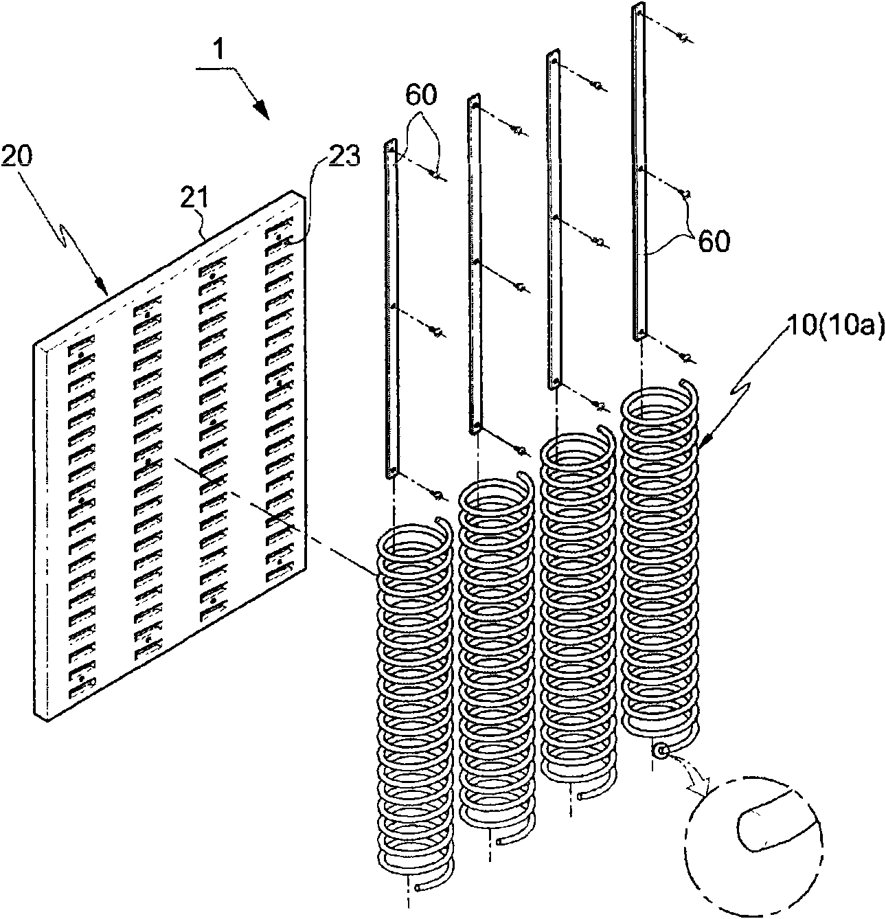
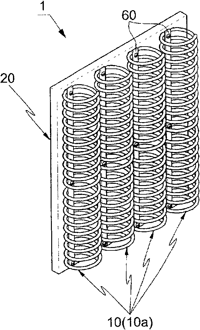
[0072] figure 1 is an exploded perspective view illustrating a heat sink having a linear heat sink unit according to an embodiment of the present invention, and figure 2 is showing figure 1 Perspective view of the assembled state.

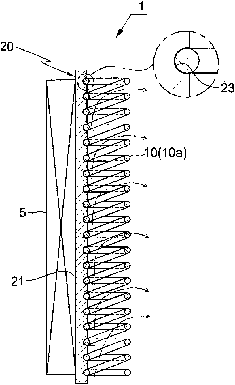
[0073] Such as figure 1 and 2 As shown in , the heat dissipation device 1 with a linear heat dissipation unit according to an embodiment of the present invention includes a heat dissipation bracket 20 having a heat absorbing portion 21, and a heat dissipation bracket 20 that is joined to the heat dissipation bracket 20 and has a spiral shape that is continuously wound by a wire. The manufactured coil-shaped linear cooling unit 10 .

[0074] The cooling bracket 20 includes an insertion h...


PUM


Abstract

A heat dissipating device having a linear heat dissipating unit and a fanless LED lamp using the device are disclosed. The heat dissipating device includes a heat dissipating bracket having a heat absorbing part, and a linear heat dissipating unit which is coupled to the heat dissipating bracket and has a coil shape achieved by the continuous winding of a wire into a spiral shape. The heat dissipating bracket includes an insert hole corresponding to part of the linear heat dissipating unit in such a way as to be in surface contact with the part of the linear heat dissipating unit, and the linear heat dissipating unit protrudes to the outside of the heat absorbing part of the heat dissipating bracket to perform a heat exchange process for dissipating heat through natural convection ventilation. The fanless LED lamp includes the linear heat dissipating unit as a heat dissipating means.

Description

technical field [0001] The present invention relates to a heat dissipation device with a linear heat dissipation unit and a fanless LED lamp using the same, wherein the linear heat dissipation unit prevents air from staying in one place in the environment without a fan and dissipates heat through natural convection ventilation so that The effective heat dissipation area is large, thus dissipating heat very effectively from electronic parts with large heat generating loads such as lamps or industrial equipment, thereby allowing the installed equipment to operate smoothly, increasing the life of the equipment, thus preventing noise pollution, and significantly Reduce manufacturing costs. Background technique [0002] Typically, electronic components such as a CPU (Central Processing Unit), thermal elements, VGA (Video Graphics Array) cards or LED lamps generate a large amount of heat during operation. When the electronic part or the LED lamp exceeds an appropriate temperature...

Claims


Application Information

Patent Timeline
Patent Type & Authority Applications(China)
IPC IPC(8): H05K7/20
CPCF21V29/2206F21V29/2231F21V29/2243F21V29/004F21K9/137H01L23/467H01L2924/0002F21Y2101/02F21K9/00F21V29/2268F21V29/2275H01L2023/4056H01L23/3677F28F3/022F21V29/74F21V29/76F21V29/773F21V29/78F21V29/80F21K9/233F21Y2115/10H01L2924/00F21V29/00
Inventor 刘泳豪
Owner FAWOO TECH CO LTD
Learn More