Energy-saving building for generating electricity by utilizing solar thermal wind

A construction and hot air technology, applied in wind power generation, buildings, building types, etc., can solve the problems of less than 20%, blockage of upper and lower water pipes, and high cost of photovoltaic cell manufacturing and use, and achieves reasonable design, convenient use, and structure. simple effect

Inactive Publication Date: 2010-04-07
赵姝珅
View PDF0 Cites 10 Cited by
  • Summary
  • Abstract
  • Description
  • Claims
  • Application Information

AI Technical Summary

Problems solved by technology

[0002] Most of the energy-saving buildings that are currently being used are to strengthen wall insulation to reduce energy loss in the building, or to install solar photovoltaic cells or solar water heaters on the roof. The useful power conversion rate of solar photovoltaic cells is low. Civilian products can't reach 20%, and the power generated can't meet the needs of providing electricity for living and office use in buildings. At the same time, the cost of manufacturing and using photovoltaic cells is relatively high, so it is not suitable for large-scale promotion and application.
However, when traditional solar water heaters are installed and used on the top floor, the upper and lower water pipes block the ventilation pipes of the bathroom. In addition, the various solar heat collecting surfaces on the roof also destroy the cleanliness and beauty of urban buildings.

Method used


Image

  • Energy-saving building for generating electricity by utilizing solar thermal wind
  • Energy-saving building for generating electricity by utilizing solar thermal wind

Examples


Embodiment

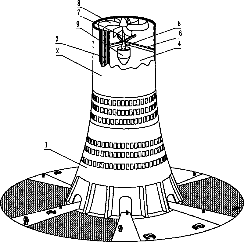
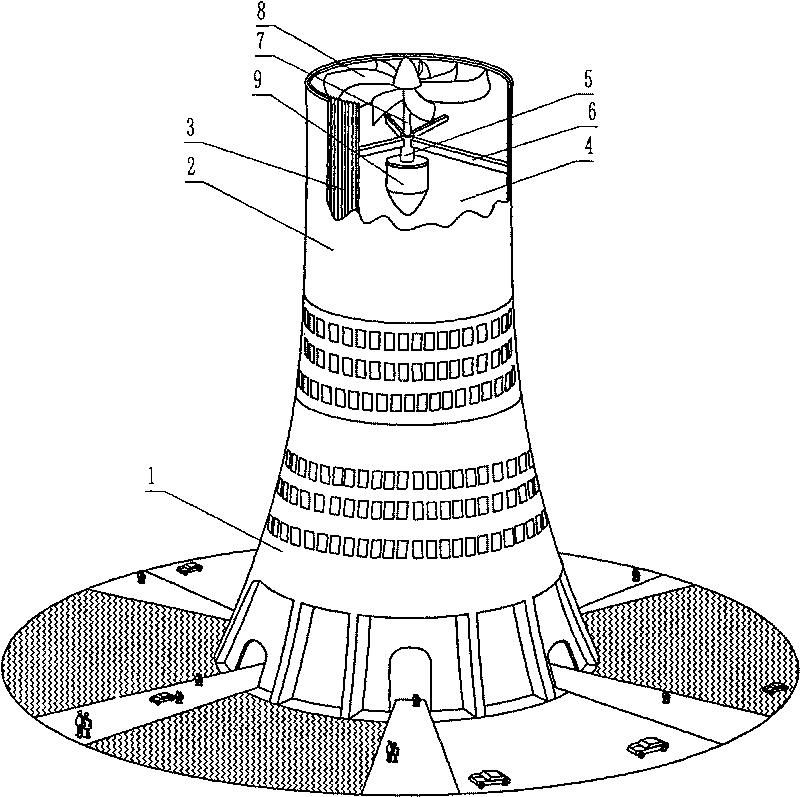
[0015] Embodiment: The structure is as shown in the accompanying drawings, consisting of a barrel-shaped building body 1, a transparent layer 2, a heat-absorbing layer 3, a hot air flow channel 4, a worm gear bushing 5, a bushing bracket 6, a worm gear shaft 7, a worm gear 8 and power generation machine 9, wherein the transparent layer 2 is connected to the barrel-shaped building body 1, the heat-absorbing layer 3 is arranged on the inner wall of the transparent layer 2, and the heat-absorbing layer 3 rolled into a barrel shape forms a hot air flow channel 4, and the worm gear sleeve 5 is connected with the shaft sleeve bracket 6, and the shaft sleeve bracket 6 is connected with the heat absorbing layer 3. The worm gear shaft sleeve 5 is provided with a worm gear shaft 7, and one end of the worm gear shaft 7 is connected with the worm gear 8, and the other end is connected with the generator 9. When in use, after the transparent layer on the upper part of the barrel-shaped buil...


PUM


Abstract

The invention relates to an energy-saving building for generating electricity by utilizing solar thermal wind, and belongs to the technical field of the manufacture of novel energy-saving buildings. The energy-saving building consists of a cylindrical building main body, a transparent layer, a heat absorption layer, a hot airflow channel, a worm-wheel shaft sleeve, a shaft sleeve support, a worm-wheel shaft, a worm wheel and a generator, wherein the transparent layer is connected with the cylindrical building main body; the heat absorption layer is arranged on the inner wall of the transparent layer; the heat absorption layer rolled into a cylindrical shape forms the hot airflow channel; the worm-wheel shaft sleeve is connected with the shaft sleeve support which is connected with the heat absorption layer; and the inside of the worm-wheel shaft sleeve is provided with the worm-wheel shaft of which one end is connected with the worm wheel and the other end is connected with the generator. When the energy-saving building is used, after the transparent layer is radiated by sunlight, infrared rays in the sunlight pass through the transparent layer and reach the heat absorption layer, air in the hot airflow channel is heated to become light and is raised in the hot airflow channel, cold air enters the channel for supplementation through a gate on the bottom layer of the building, and the raising hot airflow pushes the worm wheel to rotate so as to drive the generator on the worm-wheel shaft to rotate for generating the electricity. The energy-saving building has the advantages of reasonable design, simple structure, convenient use and the like.

Description

technical field [0001] The invention relates to an energy-saving building using solar hot wind to generate electricity, and belongs to the technical field of new energy-saving building manufacturing. Background technique [0002] Most of the energy-saving buildings that are currently being used are to strengthen wall insulation to reduce energy loss in the building, or to install solar photovoltaic cells or solar water heaters on the roof. The useful power conversion rate of solar photovoltaic cells is low. Civilian goods can't reach 20%, and the power generated can't meet the needs of providing electricity for living and office use for buildings. Meanwhile, the cost of manufacturing and using photovoltaic cells is relatively high, which is not suitable for large-scale promotion and application. And traditional solar water heater is installed and used on the top floor, and the upper and lower water pipes block the ventilation pipe of the toilet. In addition, various solar he...

Claims


Application Information

Patent Timeline
Patent Type & Authority Applications(China)
IPC IPC(8): E04H1/00F03D9/00F03D9/25F03D9/37
CPCY02B10/70Y02E10/725Y02E10/72Y02B10/30Y02P70/50
Inventor 赵姝珅
Owner 赵姝珅
Why Eureka
Try Eureka