Current vector control device and control method of power return

A technology of current vector and control device, applied in AC motor control, control system, irreversible DC power input conversion into AC power output and other directions, can solve the problem of difficulty in ensuring the accuracy and quality of feedback current control, system dynamic performance and anti-interference Poor performance, affecting the system control effect, etc.

Inactive Publication Date: 2010-04-07
德力西(杭州)变频器有限公司
View PDF0 Cites 12 Cited by
  • Summary
  • Abstract
  • Description
  • Claims
  • Application Information

AI Technical Summary

Problems solved by technology

The existing energy feedback braking device adopts the scheme of switching the power tube Bang-Bang according to the set value of the current. Although the control method and control circuit are relatively simple, it is difficult to guarantee the control accuracy and quality of the feedback current, resulting in the dynamics of the system. The performance and anti-interference performance are poor; or the grid voltage is sampled, the zero-crossing point of the voltage is captured, and the feedback current is controlled. This method has the problem of inaccurate detection of the zero-crossing point, which affects the control effect of the system.

Method used


Image

  • Current vector control device and control method of power return
  • Current vector control device and control method of power return
  • Current vector control device and control method of power return

Examples


Embodiment 1

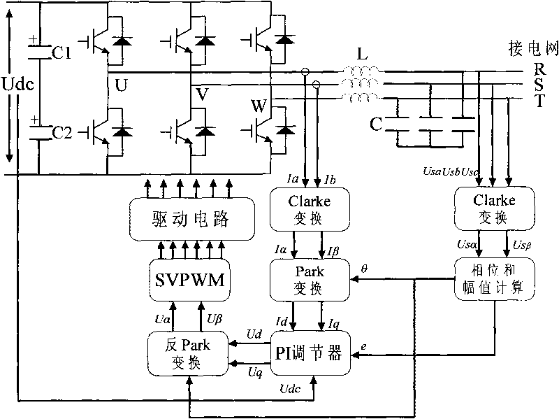
[0038] Embodiment 1: refer to Figure 1~3 . The current vector control device for energy feedback includes an inverter circuit, the output voltage U, V, W of the inverter circuit is respectively connected to one end of the reactor L, and the three-phase voltage R, S, T of the power grid is respectively connected to the reactor L The other end is connected, and the high-frequency filter capacitor C is connected to the connection between the filter reactor L and the three-phase voltage R, S, and T of the grid. The current vector control device also includes a clarke transformation module, a phase and amplitude calculation module, and a Park Transformation module, PI regulator, inverse Park transformation module, space voltage vector modulation module and drive circuit, the U of the three-phase voltage of the power grid sa , U sb and U sc The voltage output terminals of the Clarke transformation module are respectively connected with the Clarke transformation module, and the o...

Embodiment 2

[0039] Embodiment 2: refer to Figure 1~4 . The current vector control method of energy feedback, its whole processing sampling includes the following steps:

[0040] 1) U sa , U sb and U sc is the three-phase voltage of the power grid, and after Clarke transformation, U in the static coordinate system is obtained sα and U sβ :

[0041] U sα U sβ = 2 3 1 - 1 2 - 1 2 0 ...

Embodiment 3

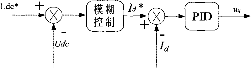
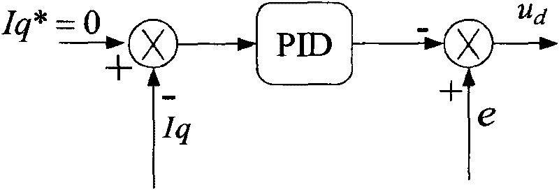
[0060] Embodiment 3: refer to Figure 4 . Because the reactor ignores the internal resistance, the current lags the voltage by 90°, where is the inverter output voltage, is the grid voltage. The d-axis component of the voltage output by the inverter U d and When equal, I q =0; at this time by adjusting U q , you can control the I d size. This enables independent control of active and reactive currents.


PUM


Abstract

The invention relates to a control device and a control method for the feedback device of a drive motor, in particular to a current vector control device and a control method driving a motor to return power. The current vector control device comprises an inverter circuit, a clarke converter module, a phase position and amplitude calculation module, a Park converter module, a PI adjuster, an anti-Park converter module, a space voltage vector modulation module and a driving circuit. The invention has the advantages that the invention realizes independent control of active current and reactive current, has short current response time and high control precision and power factor, can accurately track power grid voltage, has small pollution to power grid harmonic wave and the like.

Description

technical field [0001] The invention relates to a control device and a control method for a drive motor feedback device, in particular to a current vector control device and a control method for drive motor energy feedback. Background technique [0002] Frequency converters have been widely used in various fields of industrial and agricultural production to drive motors or as variable frequency power supplies. Most general-purpose inverters are voltage-type AC-DC-AC inverters. This topology prevents the inverter from being directly used in speed regulation occasions that require fast starting and braking and frequent forward and reverse rotation. Because when the motor decelerates and brakes, the motor is in the state of regenerative power generation, and the energy transmission of the uncontrolled rectifier is irreversible. The generated regenerative power is transmitted to and continuously stored in the DC side filter capacitor to generate a pumping voltage. Excessive pump...

Claims


Application Information

Patent Timeline
Patent Type & Authority Applications(China)
IPC IPC(8): H02M7/53H02P27/06
Inventor 黄其福段龙马永超
Owner 德力西(杭州)变频器有限公司
Why Eureka
Try Eureka