Large deflection loose tube compensation joint

A technology for compensating joints and large deflection, which is applied in the direction of expansion compensation devices for pipes/pipe joints/fittings, pipelines, adjustable connections, etc., which can solve the problems of large material consumption, easy dripping, and small compensation amount of wave compensators And other issues

Inactive Publication Date: 2010-04-14
WUXI JINYANG PIPING FITTING
View PDF0 Cites 10 Cited by
  • Summary
  • Abstract
  • Description
  • Claims
  • Application Information

AI Technical Summary

Problems solved by technology

[0003] The purpose of the present invention is to provide a large deflection pipeline connection joint, which solves the problem that other types of compensators consume a lot of materials, occupy a large

Method used


Image

  • Large deflection loose tube compensation joint
  • Large deflection loose tube compensation joint
  • Large deflection loose tube compensation joint

Examples


Embodiment Construction

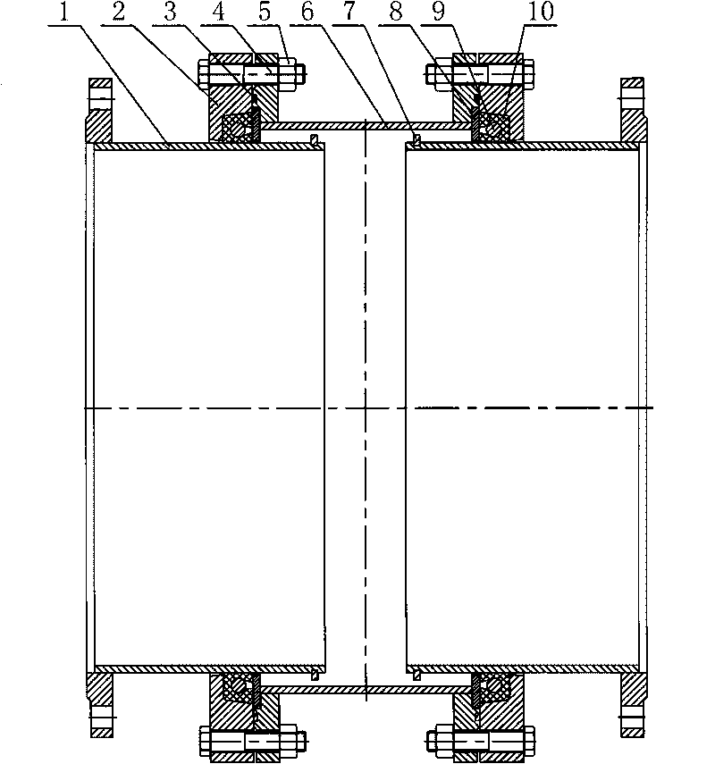
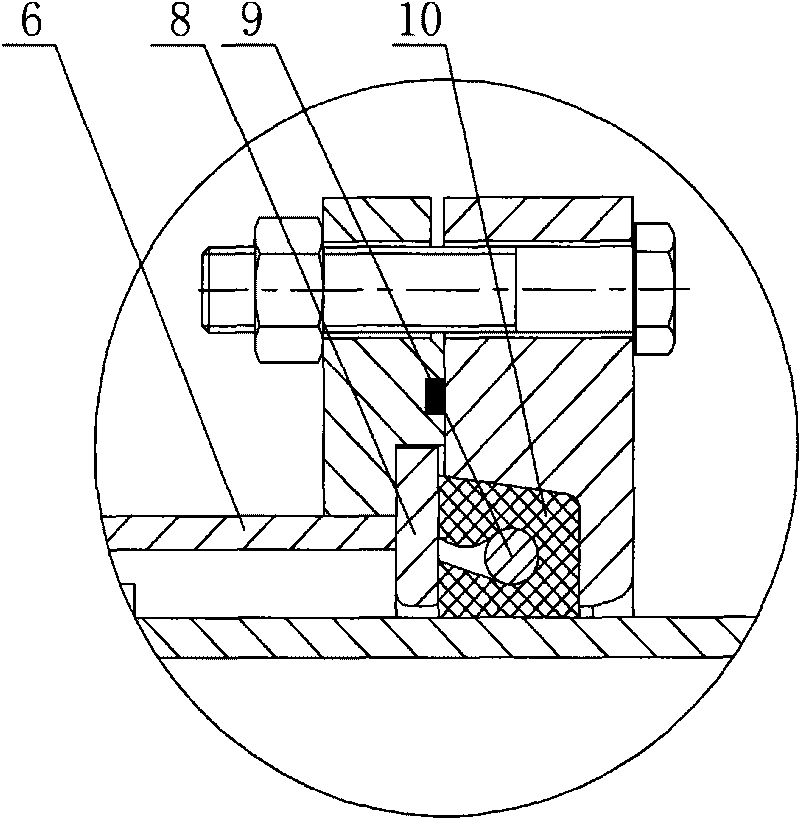
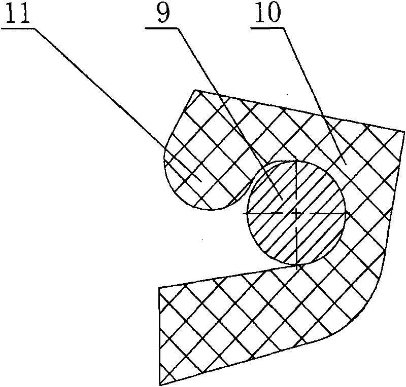
[0012] Such as figure 1 , 2 As shown, a large deflection loose sleeve compensating joint according to the present invention includes a cylindrical body 6, and the inside of the body 6 passes through two movable short pipes 1 with flanges, and the flanges are located at the ends of the short pipes 1 Both ends; the connection ends on both sides of the body 6 are respectively connected to a gland with bolts 4 and tightened with nuts 5. A ring of sealing strips 3 is provided on the connection surface between the body 6 and the gland 2; the inner sides of the two ends of the body 6 are respectively A retaining ring 8 is installed, and the retaining ring 8 is sleeved on the outside of the short pipe 1, and a limit block 7 is installed on the short pipe 1, and the limit block 7 interferes with the retaining ring 8, thereby preventing the short pipe from 1 slips off from the body 6; a sealing ring 10 is installed between the retaining ring 8 and the gland 2, the sealing ring 10 is U-...


PUM


Abstract

Disclosed is a large deflection loose tube compensation joint which comprises a cylindrical body. Two movable short pipes equipped with flanges pass through the inner portion of the body; connecting ends positioned on two sides of the body are respectively connected with pressure covers via bolts and screwed tightly via nuts, a circle of sealing strips are disposed on connecting surfaces of the body and the pressure covers; two retaining rings are respectively installed on the inner sides of two end surfaces of the body and sleeved on the outer sides of the short pipes, limit blocks are mounted on the short pipes; sealing rings mounted among the retaining rings and the pressure covers are U-shaped and embedded into rectangular grooves inside the pressure covers, the sealing rings contact with the outer walls of the short pipes, contacting surfaces of the sealing rings and the outer walls of the short pipes are cylindrical surfaces, O-shaped sealing strips are installed inside the sealing rings, projected lips are arranged on the inner surfaces of the upper portions of the sealing rings, the lips are capable of preventing the sealing strips from shedding off the sealing rings, thereby the sealing strips are capable of guaranteeing the sealing rings to produce continuous pre-tightening force on the outer walls of the short pipes and further ensuring tightness of the body and inner cavities of the short pipes.

Description

technical field [0001] The invention relates to a pipeline connection joint. Background technique [0002] Due to serious ground subsidence, large vibration, complex terrain, seasonal changes and large temperature difference between day and night, the pipeline deflection and thermal expansion and contraction will have a serious impact on the pipeline, so a compensator must be installed on the pipeline to compensate for the pipeline's deflection. Axial displacement and deflection angle eccentricity. Existing compensators mainly include square compensators, packing sleeve type compensation joints, wave compensators, L-type compensators, Z-type compensators and flexible pipe compensators. The square compensator is sturdy and durable, reliable in operation, but consumes a lot of materials and occupies a large area. It takes man-hours to manufacture a large-diameter square compensator, so it is suitable for small-diameter and high-pressure pipelines; the packing sleeve type comp...

Claims


Application Information

Patent Timeline
IPC IPC(8): F16L27/12F16L51/00
Inventor 王锡铭刘国中蔡建忠沈立盛周建明杨士立
Owner WUXI JINYANG PIPING FITTING
Why Eureka
Try Eureka