Energy storage system for utilizing fire control water tank to realize storage of cold and heat

A fire-fighting water tank and heat storage technology, applied in the field of energy storage systems, can solve problems such as being unable to be effectively utilized, and achieve the effects of reducing space occupation and initial investment.

Inactive Publication Date: 2010-04-14
上海华电源牌环境工程有限公司
View PDF0 Cites 5 Cited by
  • Summary
  • Abstract
  • Description
  • Claims
  • Application Information

AI Technical Summary

Problems solved by technology

The water stored in this fire water tank cannot be effectively used under normal conditions
The published literature shows that there is no energy storage system that can use the fire water tank to simultaneously store heat and cold, that is, use the water stored in the fire water tank as the medium for heat storage and cold storage

Method used


Image

  • Energy storage system for utilizing fire control water tank to realize storage of cold and heat
  • Energy storage system for utilizing fire control water tank to realize storage of cold and heat
  • Energy storage system for utilizing fire control water tank to realize storage of cold and heat

Examples


Embodiment Construction

[0014] The features of the present invention and other related features will be further described in detail below in conjunction with the accompanying drawings through embodiments, so as to facilitate the understanding of those skilled in the art:

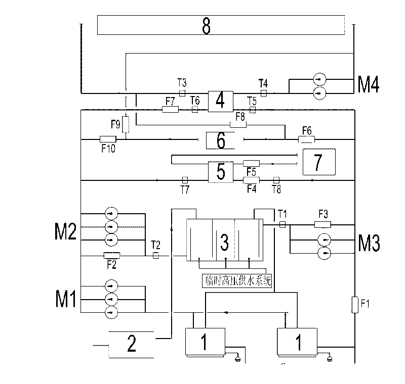
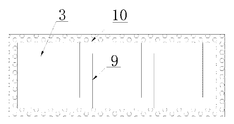
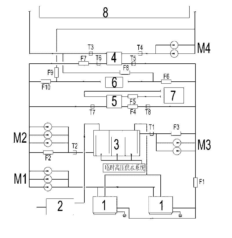
[0015] Such as Figure 1-2 As shown, the labels respectively indicate: electric boiler 1, water softener 2, fire water tank 3, heating plate heat exchanger 4, cold storage plate heat exchanger 5, fresh air treatment unit 6, electric refrigeration main unit 7, heating air conditioner 8, insulation Plate 9, insulation layer 10, electric valve: F1, F2, F3, F4, F5, F6, F7, F8, F9, F10; temperature sensor: T1, T2, T3, T4, T5, T6, T7, T8; pump Groups M1, M2, M3, M4.

[0016] Such as figure 1 As shown, the pump sets in this embodiment are composed of several water pumps connected in parallel, wherein the pump sets M1 and M2 are composed of 3 pumps; the pump sets M3 and M4 are composed of 3 pumps, which operate under different working co...


PUM


Abstract

The invention relates to the electric energy storage technique and particularly relates to an energy storage system for utilizing a fire control water tank to realize storage of cold and heat, wherein the energy storage system is applicable to a high-rise building provided with a fire control water tank, and comprises a heat supply plate type heat exchanger and at least one electric boiler, wherein the heat supply plate type heat exchanger is connected with a heat supply air conditioner. The system is characterized in that the energy storage system further comprises a cold storage plate type heat exchanger and a new air processor set, the cold storage plate type heat exchanger, the new air processor set, the heat supply plate type heat exchanger, the electric boiler and the fire control water tank are connected in parallel, the cold storage plate type heat exchanger is connected with a refrigeration device, the system has the advantages that a common fire control water tank is used as a heat storage and a cold storage device, two energy storage modes of storing heat and storing cold can be realized simultaneously on one set of system, the initial investment of the system can be effectively lowered, and the space occupation of the system can be reduced simultaneously.

Description

technical field [0001] The invention relates to an electric energy storage technology, in particular to an energy storage system utilizing a fire-fighting water tank to realize cold storage and heat storage. Background technique [0002] The heat storage system means that all or part of the heat (or cold) required by the building during the day is prepared at night (low power period) and stored in the form of hot water (or cold water and ice) for use during the day. Energy storage technology has unique advantages in alleviating peak-valley electricity contradictions. At present, starting from the control of coal and fuel consumption to effectively prevent pollution, the state has decided to gradually limit the number, capacity, and area of ​​use of coal and oil-fired boilers in large and medium-sized cities, vigorously develop clean energy, and improve the environment. As part of the market economy, government departments also use price levers to macro-control the energy st...

Claims


Application Information

Patent Timeline
Patent Type & Authority Applications(China)
IPC IPC(8): F24F5/00E03B11/00
Inventor 戴自挺奚玉娟韩云海尤康杰张力峰
Owner 上海华电源牌环境工程有限公司
Why Eureka
Try Eureka