Fixing device of optical detector

An optical detector and fixing device technology, applied in measuring devices, scientific instruments, material analysis by optical means, etc., can solve the problems of low detection accuracy and easy shaking of various components, so as to improve detection accuracy, reduce shaking, enhance The effect of stability

Inactive Publication Date: 2010-04-21
SUZHOU MINGFU AUTOMATIC SCI & TECH
View PDF0 Cites 3 Cited by
  • Summary
  • Abstract
  • Description
  • Claims
  • Application Information

AI Technical Summary

Problems solved by technology

The fixing device effectively reduces the shaking generated during the operation, enhances the stability of the operation, improves the detection accuracy,

Method used


Image

  • Fixing device of optical detector
  • Fixing device of optical detector
  • Fixing device of optical detector

Examples


Embodiment Construction

[0013] The present invention will be described in detail below in conjunction with the accompanying drawings.

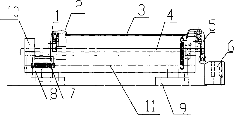
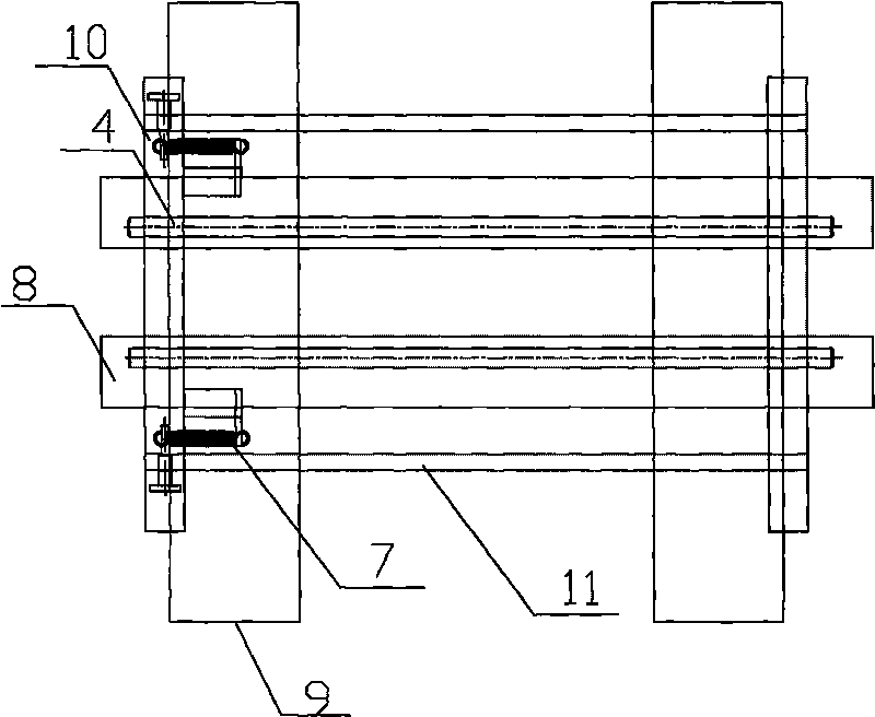
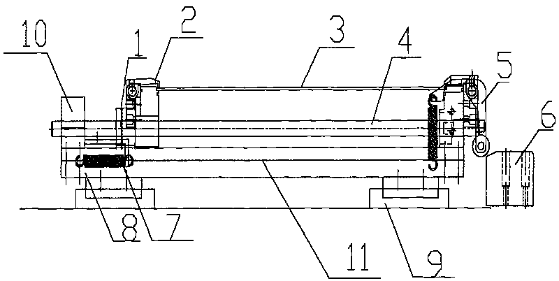
[0014] like figure 1 and figure 2 Shown are a schematic structural view and a top view of the optical detector including the fixing device of the present invention, respectively.

[0015] The fixing device of the optical detector of the present invention includes two parallel slide rails 8 positioned on the base 9 and perpendicular to the base 9, a fixture body 1 and a fixture backstage located on the parallel slide rails 8 and connected by a long connecting rod 4 and a guide rod 11 10. The pressure jaw 2 for fixing the PCB board 3 on the clamp body 1, the connecting rod 5 on the clamp body 1 and the blocking seat 6 located at the front end of the optical detector, wherein, between the clamp backstage 10 and the guide rod 11, there are Extension spring 7. The extension spring 7 is parallel to the guide rod 11 and is fixed between the fixture backstage 10 and the ...


PUM


Abstract

The invention discloses a fixing device of an optical detector, which comprises two parallel slide rails (8) which are positioned on a base (9) and are vertical to the base (9), a clamp body (1) and a clamp rear stand (10) which are positioned on the parallel slide rails (8) and are connected through a long connecting rod (4) and a guide rod (11), a pressure claw (2) for a fixed PCB (3) on the clamp body (1), a connecting rod (5) on the clamp body (1) and a blocking seat (6) positioned at the front end of the optical detector, wherein a tension spring (7) is arranged between the clamp rear stand (10) and the guide rod (11). The fixing device of the optical detector has the advantages that the provided tension spring (7) can effectively produce an acting force opposite to the force produced by extension or compression of each component of the running optical detector so as to reduce rock produced during running, enhance the running stability and improve the detection precision.

Description

technical field [0001] The invention relates to a fixing device, in particular to a fixing device for an optical detector. Background technique [0002] The optical detector is a device that detects the solder joints of the PCB board after solder joint welding. At present, the optical detector on the market mainly includes a base, two parallel slide rails vertical to the base, and a connecting rod mechanism on the parallel slide rails. The connected fixture body and the fixture background, during the detection process, the PCB board is placed on the fixture body and fixed by the fixture claws on the fixture body, and the PCB board will slide on the slide rail during the detection process. Move left and right, but the optical detectors currently on the market do not have a fixing device to fix the moving direction of the clip body on the slide rail and guide rod. Therefore, each part of the optical detector is easy to shake during the sliding process, resulting in detection ...

Claims


Application Information

Patent Timeline
IPC IPC(8): G01N21/01G01N21/84
Inventor 庄春明
Owner SUZHOU MINGFU AUTOMATIC SCI & TECH
Why Eureka
Try Eureka