Jet overflow dyeing machine nozzle

An overflow dyeing machine and nozzle technology, which is applied in textile processing machine accessories, textiles and papermaking, and textile material treatment at the outlet of textile materials. , to achieve the effect of preventing backflow, reducing "air drums" and reducing fabric kinks

Inactive Publication Date: 2010-04-28
济南元首针织股份有限公司 +1
View PDF0 Cites 5 Cited by
  • Summary
  • Abstract
  • Description
  • Claims
  • Application Information

AI Technical Summary

Problems solved by technology

[0003] 1. Since the cross-section of the commonly used nozzle is circular, when the cylindrical fabric passes through the nozzle, it will be rolled into a column, and the gas inside the fabric cannot flow out of the nozzle together with the fabric, and there is backflow in the nozzle elbow, which is easy to produce "air drum" Phenomenon
[0004] 2. Due to the different materials of the dyed fabrics, it is necessary to adjust the spraying speed of the nozzles, but the gap between the commonly used nozzles cannot be adjusted, and different nozzles must be replaced, which will cause the cost burden of the dyeing factory and the trouble of replacement

Method used


Image

  • Jet overflow dyeing machine nozzle
  • Jet overflow dyeing machine nozzle
  • Jet overflow dyeing machine nozzle

Examples


Embodiment Construction

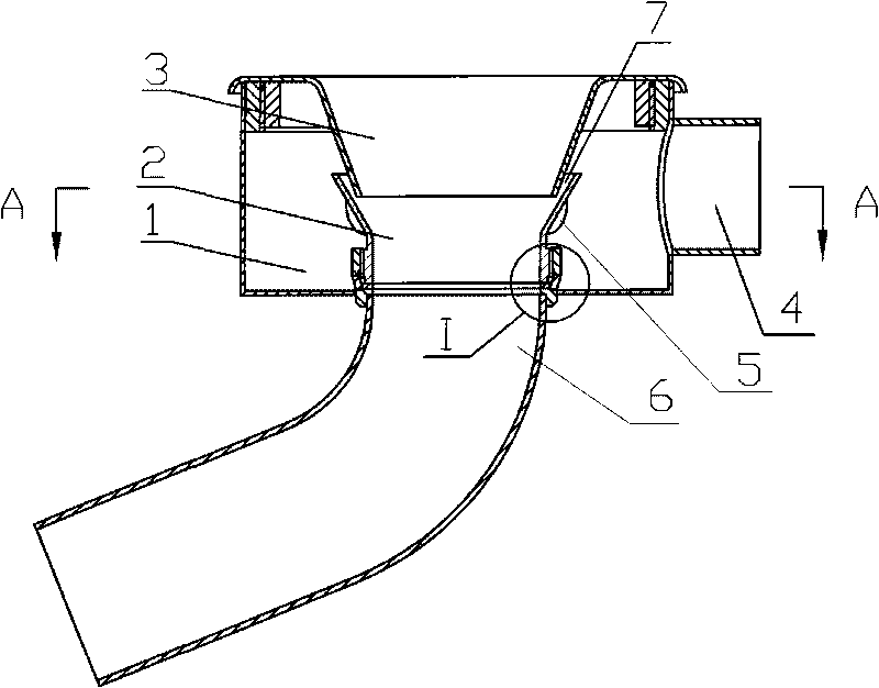
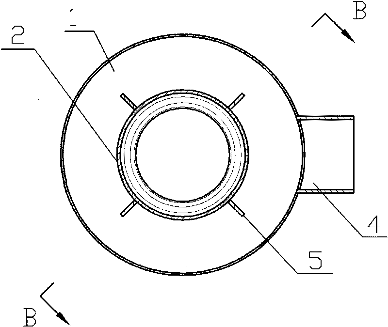
[0017] Such as Figure 1-5 A specific embodiment shown includes a nozzle seat 1 , a nozzle core seat 2 , a nozzle cover 3 , a nozzle liquid inlet pipe 4 , a water baffle 5 and a nozzle elbow 6 .

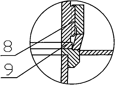
[0018] Such as figure 1 As shown, the nozzle core seat 2 and the nozzle cover 3 are arranged in the nozzle seat 1, the nozzle core seat 2 and the nozzle cover 3 are funnel-shaped, the lower end of the nozzle cover 3 is inserted in the nozzle core seat 2, the nozzle core seat 2 and the nozzle There is an annular gap between the covers 3, the annular gap is the dye solution injection inlet 7, and the side of the nozzle seat 1 is provided with a nozzle liquid inlet pipe 4. Such as figure 1 with figure 2 As shown, the bottom surface of the nozzle seat 1 is welded with a cylindrical lower support inserted on the bottom surface. The upper end of the cylindrical lower support is provided with an internal thread 8, and the middle part of the cylindrical lower support is fixed with a stop...


PUM


Abstract

The invention discloses a jet overflow dyeing machine nozzle, comprising a nozzle carrier and a nozzle core carrier and a nozzle cover which are arranged in the nozzle carrier; wherein the nozzle core carrier and the nozzle cover are in funnel shape, the lower end of the nozzle cover is inserted into the nozzle core carrier, an annular gap is arranged between the nozzle core carrier and the nozzle cover, the annular gap is a dye liquor injecting port, the nozzle carrier is provided with a nozzle fluid pipe, the lower end of the nozzle core carrier is connected with the nozzle carrier by screw thread, a spacer is arranged between the lower end face of the nozzle core carrier and the nozzle carrier, and the outer wall of the nozzle core carrier is provided with a plurality of watertight shutters separated each other. The invention can prevent reflow from being produced in curved pipe of nozzle and reduce textile kinking and 'tympany'. When installing the nozzle, the thickness of the spacer between the nozzle carrier and the nozzle core carrier is adjusted to regulate the size of the dye liquor injecting port and the angle between the watertight shutter on the nozzle core carrier and the nozzle fluid pipe, thus realizing regulation of liquid flow jet speed and pressure.

Description

technical field [0001] The invention relates to a dyeing machine nozzle, in particular to an overflow dyeing machine nozzle. Background technique [0002] The nozzle of the general overflow dyeing machine is circular, the nozzle cover and the nozzle seat are connected by screws, the nozzle core seat and the nozzle seat are welded, the gap between the nozzles is not adjustable, and there is no water baffle inside. Its main flaws are: [0003] 1. Since the cross-section of the commonly used nozzle is circular, when the cylindrical fabric passes through the nozzle, it will be rolled into a column, and the gas inside the fabric cannot flow out of the nozzle together with the fabric, and there is backflow in the nozzle elbow, which is easy to produce "air drum" Phenomenon. [0004] 2. Due to the different materials of the dyed fabrics, the spraying speed of the nozzles needs to be adjusted, but the gap between common nozzles cannot be adjusted, and different nozzles must be rep...

Claims


Application Information

Patent Timeline
Patent Type & Authority Applications(China)
IPC IPC(8): D06B23/00D06B1/08
Inventor 昃向博任泉远张朝阳孙煜杨学锋孙俊科
Owner 济南元首针织股份有限公司
Why Eureka
Try Eureka